UPSD3212C, UPSD3212CV
TIMER/COUNTERS (TIMER 0, TIMER 1 AND TIMER 2)
The uPSD321X Devices has three 16-bit Timer/
Counter registers: Timer 0, Timer 1 and Timer 2.
All of them can be configured to operate either as
timers or event counters and are compatible with
standard 8032 architecture.
In the “Timer” function, the register is incremented
every machine cycle. Thus, one can think of it as
counting machine cycles. Since a machine cycle
consists of 6 CPU clock periods, the count rate is
1/6 of the CPU clock frequency or 1/12 of Oscilla-
following the one in which the transition was de-
tected. Since it takes 2 machine cycles (24 f
OSC
clock periods) to recognize a 1-to-0 transition, the
maximum count rate is 1/24 of the f . There are
OSC
no restrictions on the duty cycle of the external in-
put signal, but to ensure that a given level is sam-
pled at least once before it changes, it should be
held for at least one full cycle. In addition to the
“Timer” or “Counter” selection, Timer 0 and Timer
1 have four operating modes from which to select.
tor Frequency (f
).
Timer 0 and Timer 1
OSC
In the “Counter” function, the register is increment-
ed in response to a 1-to-0 transition at its corre-
sponding external input pin, T0 or T1. In this
function, the external input is sampled during
S5P2 of every machine cycle. When the samples
show a high in one cycle and a low in the next cy-
cle, the count is incremented. The new count value
appears in the register during S3P1 of the cycle
The “Timer” or “Counter” function is selected by
control bits C/T in the Special Function Register
TMOD. These Timer/Counters have four operat-
ing modes, which are selected by bit-pairs (M1,
M0) in TMOD. Modes 0, 1, and 2 are the same for
Timers/ Counters. Mode 3 is different. The four op-
erating modes are de-scribed in the following text.
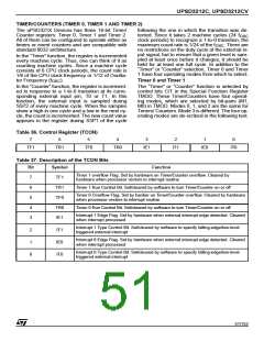
Table 36. Control Register (TCON)
7
6
5
4
3
2
1
0
TF1
TR1
TF0
TR0
IE1
IT1
IE0
IT0
Table 37. Description of the TCON Bits
Bit
Symbol
Function
Timer 1 overflow Flag. Set by hardware on Timer/Counter overflow. Cleared by
hardware when processor vectors to interrupt routine
7
TF1
6
TR1
TF0
Timer 1 Run Control Bit. Set/cleared by software to turn Timer/Counter on or off
Timer 0 Overflow Flag. Set by hardier on Timer/Counter overflow. Cleared by hardware
when processor vectors to interrupt routine
5
4
TR0
IE1
Timer 0 Run Control Bit. Set/cleared by software to turn Timer/Counter on or off
Interrupt 1 Edge Flag. Set by hardware when external interrupt edge detected. Cleared
when interrupt processed
3
Interrupt 1 Type Control Bit. Set/cleared by software to specify falling-edge/low-level
triggered external interrupt
2
1
0
IT1
IE0
IT0
Interrupt 0 Edge Flag. Set by hardware when external interrupt edge detected. Cleared
when interrupt processed
Interrupt 0 Type Control Bit. Set/cleared by software to specify falling-edge/low-level
triggered external interrupt
51/152

 STMICROELECTRONICS [ ST ]