UPSD3212C, UPSD3212CV
UPSD3200 HARDWARE DESCRIPTION
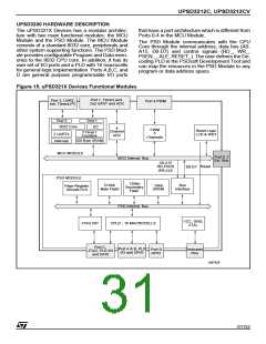
The uPSD321X Devices has a modular architec-
ture with two main functional modules: the MCU
Module and the PSD Module. The MCU Module
consists of a standard 8032 core, peripherals and
other system supporting functions. The PSD Mod-
ule provides configurable Program and Data mem-
ories to the 8032 CPU core. In addition, it has its
own set of I/O ports and a PLD with 16 macrocells
for general logic implementation. Ports A,B,C, and
D are general purpose programmable I/O ports
that have a port architecture which is different from
Ports 0-4 in the MCU Module.
The PSD Module communicates with the CPU
Core through the internal address, data bus (A0-
A15, D0-D7) and control signals (RD_, WR_,
PSEN_ , ALE, RESET_). The user defines the De-
coding PLD in the PSDsoft Development Tool and
can map the resources in the PSD Module to any
program or data address space.
Figure 15. uPSD321X Devices Functional Modules
Port 1, Timers and
2nd UART and ADC
Port 3, UART,
Port 4 PWM
2
Intr, Timers,I C
Port 3
Port 1
I2C
3 Timer /
8032 Core
4
PWM
Reset Logic
LVD & WDT
Channel
5
2 UARTs
ADC
Counters
256 Byte SRAM
Channels
Interrupt
MCU MODULE
Port 0, 2
Ext. Bus
8032 Internal Bus
A0-A15
RD,PSEN
WR,ALE
Reset
D0-D7
PSD MODULE
128Kb
Secondary
Flash
Bus
Interface
512Kb
Main Flash
16Kb
SRAM
Page Register
Decode PLD
PSD Internal Bus
VCC, GND,
JTAG ISP
CPLD - 16 MACROCELLS
XTAL
Port C,
JTAG, PLD I/O
and GPIO
Port A & B, PLD
I/O and GPIO
Port D
GPIO
Dedicated
Pins
AI07426
31/152

 STMICROELECTRONICS [ ST ]