UPSD3212C, UPSD3212CV
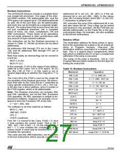
Jump Instructions
Table 13 shows the list of unconditional jump in-
structions. The table lists a single “JMP add” in-
struction, but in fact there are three SJMP, LJMP,
and AJMP, which differ in the format of the desti-
nation address. JMP is a generic mnemonic which
can be used if the programmer does not care
which way the jump is en-coded.
The SJMP instruction encodes the destination ad-
dress as a relative offset, as described above. The
instruction is 2 bytes long, consisting of the op-
code and the relative offset byte. The jump dis-
tance is limited to a range of -128 to +127 bytes
relative to the instruction following the SJMP.
The LJMP instruction encodes the destination ad-
dress as a 16-bit constant. The instruction is 3
bytes long, consisting of the opcode and two ad-
dress bytes. The destination address can be any-
where in the 64K Program Memory space.
The AJMP instruction encodes the destination ad-
dress as an 11-bit constant. The instruction is 2
bytes long, consisting of the opcode, which itself
contains 3 of the 11 address bits, followed by an-
other byte containing the low 8 bits of the destina-
tion address. When the instruction is executed,
these 11 bits are simply substituted for the low 11
bits in the PC. The high 5 bits stay the same.
Hence the destination has to be within the same
2K block as the instruction following the AJMP.
The RL A instruction converts the index number (0
through 4) to an even number on the range 0
through 8, because each entry in the jump table is
2 bytes long:
JUMP TABLE:
AJMP CASE 0
AJMP CASE 1
AJMP CASE 2
AJMP CASE 3
AJMP CASE 4
Table 13 shows a single “CALL addr” instruction,
but there are two of them, LCALL and ACALL,
which differ in the format in which the subroutine
address is given to the CPU. CALL is a generic
mnemonic which can be used if the programmer
does not care which way the address is encoded.
The LCALL instruction uses the 16-bit address for-
mat, and the subroutine can be anywhere in the
64K Program Memory space. The ACALL instruc-
tion uses the 11-bit format, and the subroutine
must be in the same 2K block as the instruction fol-
lowing the ACALL.
In any case, the programmer specifies the subrou-
tine address to the assembler in the same way: as
a label or as a 16-bit constant. The assembler will
put the address into the correct format for the giv-
en instructions.
In all cases the programmer specifies the destina-
tion address to the assembler in the same way: as
a label or as a 16-bit constant. The assembler will
put the destination address into the correct format
for the given instruction. If the format required by
the instruction will not support the distance to the
specified destination address, a “Destination out
of range” message is written into the List file.
The JMP @A+DPTR instruction supports case
jumps. The destination address is computed at ex-
ecution time as the sum of the 16-bit DPTR regis-
ter and the Accumulator. Typically. DPTR is set up
with the address of a jump table. In a 5-way
branch, for ex-ample, an integer 0 through 4 is
loaded into the Accumulator. The code to be exe-
cuted might be as follows:
Subroutines should end with a RET instruction,
which returns execution to the instruction following
the CALL.
RETI is used to return from an interrupt service
routine. The only difference between RET and
RETI is that RETI tells the interrupt control system
that the interrupt in progress is done. If there is no
interrupt in progress at the time RETI is executed,
then the RETI is functionally identical to RET.
Table 13. Unconditional Jump Instructions
Mnemonic
JMP addr
JMP @A+DPTR
CALL addr
RET
Operation
Jump to addr
Jump to A+DPTR
Call Subroutine at addr
Return from subroutine
Return from Interrupt
No operation
MOV DPTR,#JUMP TABLE
MOV A,INDEX_NUMBER
RL A
JMP @A+DPTR
RETI
NOP
28/152

 STMICROELECTRONICS [ ST ]