TS5070 - TS5071
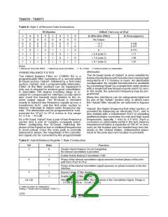
formerand the impedanceof the 2Wloop,ZL. Ifthe
impedance reflected back into the transformer pri-
mary is expressed as ZL’ then the echo path trans-
fer function from VFRO to VFXI is :
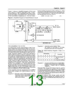
Figure 1 shows a simplified diagram of the local
echo path for a typical application with a trans-
former interface. The magnitude and phase of the
local echo signal, measured at VFXI, area function
of the termination impedance ZT, the line trans-
H(W) = ZL’ /(ZT + ZL’)
(1)
Figure 1: Simplified Diagram of Hybrid Balance Circuit
PROGRAMMING THE FILTER
Register2: select/de-select Hybal1 filter;
set Hybal1 to Bi-Quad or 1st order;
program pole and zero frequency.
On initial power-up the Hybrid Balance filter is dis-
abled. Before the hybrid balance filter can be pro-
grammed it is necessary to design the transformer
and terminationimpedancein orderto meetsystem
2 W input return loss specifications,which are nor-
mally measured against a fixed test impedance
Table 10: Hybrid Balance Register 2 Byte 2 in-
structions
Bit Number
Function
Ω
(600or 900 inmost countries).Onlythencan the
7
6
5
4
3
2
1
0
echo path be modeledand the hybridbalancefilter
programmed. Hybrid balancing is also measured
against a fixed test impedance, specified by each
national Telecom administration to provide ade-
quate control of talker and listener echo over the
majority of their network connections.This test im-
pedance is ZL in figure 1. The echo signal and the
degree of transhybrid loss obtained by the pro-
grammable filter must be measured from the PCM
digital input DR0, to the PCM digital output DX0,
either bydigitaltest signalanalysisorby conversion
back to analog by a PCM CODEC/Filter.
0
0
0
0
0
0
0
0
By Pass Hybal 1
Filter
X
X
X
X
X
X
X
X
Pole/zero Setting
Register 3 : programpolefrequencyin Hybal2 filter;
programzero frequencyin Hybal2 filter;
settings = Please refer to software
TS5077-2.
Standard filter design techniques may be used to
modelthe echo path (see equation(1)) and design
a matchinghybridbalancefilterconfiguration.Alter-
natively, the frequency response of the echo path
can be measuredand the hybrid balance filter pro-
grammed to replicate it.
Three registers must be programmed in COMBO
IIG to fully configure the Hybrid Balance Filter as
follows :
Register 1: select/de-select Hybrid Balance Filter;
invert/non-invert cancellation signal;
select/de-select Hybal2 filter section;
attenuatorsetting.
An Hybrid Balance filter design guide and soft-
ware optimization program are available under li-
cense from SGS-THOMSON Microelectronics (or-
der TS5077-2).
13/32

 STMICROELECTRONICS [ ST ]