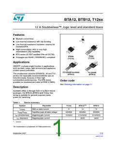
BTA12, BTB12, T12xx
Characteristics
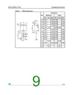
Table 4.
Symbol
Electrical characteristics (T = 25°C, unless otherwise specified)
j
standard (4 quadrants)
BTA12 / BTB12
Test Conditions
Quadrant
Unit
C
B
I - II - III
IV
25
50
50
100
(1)
IGT
MAX.
mA
VD = 12 V
RL = 30 Ω
VGT
VGD
ALL
ALL
MAX.
MIN.
1.3
0.2
V
V
VD = VDRM RL = 3.3 kΩ Tj = 125° C
(2)
IH
IT = 500 mA
MAX.
25
40
80
200
5
50
50
mA
I - III - IV
II
IL
IG = 1.2 IGT
MAX.
mA
100
400
10
dV/dt (2)
VD = 67% VDRM gate open Tj = 125° C
MIN.
MIN.
V/µs
V/µs
(dV/dt)c (2) (dI/dt)c = 5.3 A/ms Tj = 125° C
1. Minimum IGT is guaranted at 5% of IGT max.
2. for both polarities of A2 referenced to A1.
Table 5.
Symbol
Static characteristics
Test conditions
Tj = 25° C
Value
Unit
(1)
(1)
(1)
VT
Vt0
Rd
ITM = 17 A
tp = 380 µs
MAX.
1.55
0.85
35
5
V
V
Threshold voltage
Tj = 125° C
Tj = 125° C
Tj = 25° C
Tj= 125° C
MAX.
MAX.
Dynamic resistance
mΩ
µA
mA
IDRM
IRRM
VDRM = VRRM
MAX.
1
1. for both polarities of A2 referenced to A1
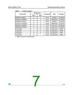
Table 6.
Symbol
Thermal resistance
Parameter
Value
Unit
I2PAK / D2PAK / TO-220AB
1.4
2.3
45
Rth(j-c)
Junction to case (AC)
Junction to ambient
°C/W
TO-220AB insulated
S(1) = 1 cm2 D2PAK
TO-220AB / I2PAK
Rth(j-a)
°C/W
60
TO-220AB insulated
1. Copper surface under tab.
3/12

 STMICROELECTRONICS [ ST ]