STM8S903K3 STM8S903F3
Electrical characteristics
Symbol Parameter
Conditions
Typ
0.7
Max(1) Unit
fADC = 6 MHz
fADC = 2 MHz
fADC = 4 MHz
fADC = 6 MHz
1.5
1.5
2
|EL|
Integral linearity error(2)
0.6
0.8
0.8
2
(1) Data based on characterisation results, not tested in production.
(2) ADC accuracy vs. negative injection current: Injecting negative current on any of the
analog input pins should be avoided as this significantly reduces the accuracy of the
conversion being performed on another analog input. It is recommended to add a Schottky
diode (pin to ground) to standard analog pins which may potentially inject negative current.
Any positive injection current within the limits specified for IINJ(PIN) and ΣIINJ(PIN) in the I/O
port pin characteristics section does not affect the ADC accuracy.
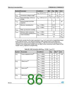
Table 49: ADC accuracy with RAIN < 10 kΩ RAIN, VDD = 3.3 V
Symbol Parameter
Conditions
Typ
1.6
Max(1) Unit
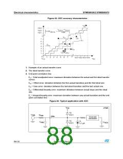
|ET|
|EO|
|EG|
|ED|
|EL|
Total unadjusted error
fADC = 2 MHz
fADC = 4 MHz
fADC = 2 MHz
fADC = 4 MHz
fADC = 2 MHz
fADC = 4 MHz
fADC = 2 MHz
fADC = 4 MHz
fADC = 2 MHz
fADC = 4 MHz
3.5
4
LSB
1.9
1
Offset error
2.5
2.5
3
1.5
1.3
2
Gain error
3
Differential linearity error
Integral linearity error
0.7
0.7
0.6
0.8
1
1.5
1.5
2
(1) Data based on characterisation results, not tested in production.
DocID15590 Rev 8
87/116

 STMICROELECTRONICS [ ST ]