Electrical characteristics
Table 46.
STM32F105xx, STM32F107xx
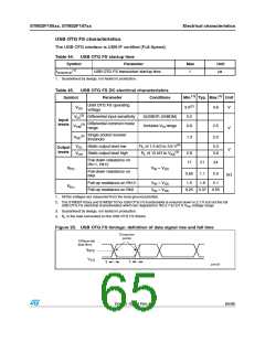
USB OTG FS electrical characteristics(1)
Driver characteristics
Symbol
Parameter
Rise time(2)
Fall time(2)
Conditions
Min
Max
Unit
tr
tf
CL = 50 pF
CL = 50 pF
tr/tf
4
4
20
20
ns
ns
%
V
trfm
VCRS
Rise/ fall time matching
90
1.3
110
2.0
Output signal crossover voltage
1. Guaranteed by design, not tested in production.
Measured from 10% to 90% of the data signal. For more detailed informations, please refer to USB
Specification - Chapter 7 (version 2.0).
2.
Ethernet characteristics
Table 47 showns the Ethernet operating voltage.
Table 47. Ethernet DC electrical characteristics
Symbol
Input level
Parameter
Min.(1)
Max.(1)
Unit
VDD
Ethernet operating voltage
3.0
3.6
V
1. All the voltages are measured from the local ground potential.
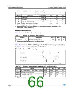
Table 48 gives the list of Ethernet MAC signals for the SMI (station management interface)
and Figure 26 shows the corresponding timing diagram.
Figure 26. Ethernet SMI timing diagram
t
MDC
ETH_MDC
t
d(MDIO)
ETH_MDIO(O)
t
t
su(MDIO)
h(MDIO)
ETH_MDIO(I)
ai15666c
(1)
Table 48. Dynamics characteristics: Ethernet MAC signals for SMI
Symbol
Rating
Min
Typ
583.3
Max
584
Unit
ns
tMDC
MDC cycle time (1.71 MHz, AHB = 72 MHz) 582.8
td(MDIO) MDIO write data valid time
tsu(MDIO) Read data setup time
th(MDIO) Read data hold time
1. TBD stands for to be determined.
305.2
TBD
TBD
305.9
TBD
TBD
306.5
TBD
TBD
ns
ns
ns
66/95
Doc ID 15274 Rev 4

 STMICROELECTRONICS [ ST ]