STM32F405xx, STM32F407xx
Package characteristics
6.2
Thermal characteristics
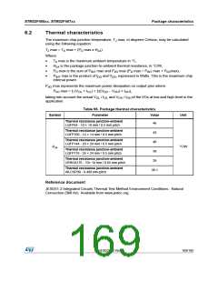
The maximum chip-junction temperature, T max, in degrees Celsius, may be calculated
J
using the following equation:
T max = T max + (P max x Θ )
J
A
D
JA
Where:
•
•
•
•
T max is the maximum ambient temperature in °C,
A
Θ
is the package junction-to-ambient thermal resistance, in °C/W,
JA
P max is the sum of P
max and P max (P max = P
max + P max),
INT I/O
D
INT
I/O
D
P
max is the product of I and V , expressed in Watts. This is the maximum chip
DD DD
INT
internal power.
P
max represents the maximum power dissipation on output pins where:
I/O
P
max = Σ (V × I ) + Σ((V – V ) × I ),
OL OL DD OH OH
I/O
taking into account the actual V / I and V / I of the I/Os at low and high level in the
OL OL
OH OH
application.
Table 96. Package thermal characteristics
Symbol
Parameter
Value
Unit
Thermal resistance junction-ambient
LQFP64 - 10 × 10 mm / 0.5 mm pitch
46
43
Thermal resistance junction-ambient
LQFP100 - 14 × 14 mm / 0.5 mm pitch
Thermal resistance junction-ambient
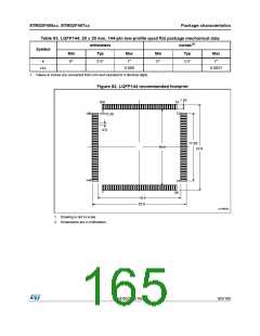
LQFP144 - 20 × 20 mm / 0.5 mm pitch
40
ΘJA
°C/W
Thermal resistance junction-ambient
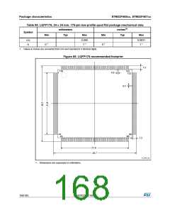
LQFP176 - 24 × 24 mm / 0.5 mm pitch
38
Thermal resistance junction-ambient
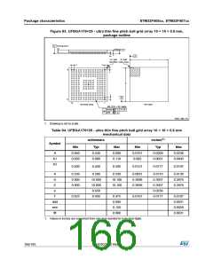
UFBGA176 - 10× 10 mm / 0.65 mm pitch
39
Thermal resistance junction-ambient
WLCSP90 - 0.400 mm pitch
38.1
Reference document
JESD51-2 Integrated Circuits Thermal Test Method Environment Conditions - Natural
Convection (Still Air). Available from www.jedec.org.
DocID022152 Rev 4
169/185

 STMICROELECTRONICS [ ST ]