Electrical characteristics
STM32F302xx/STM32F303xx
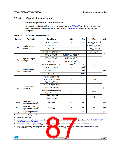
Table 51. I/O current injection susceptibility
Functionalsusceptibility
Unit
Symbol
Description
Negative
injection
Positive
injection
Injected current on BOOT0
– 0
NA
Injected current on PC0, PC1, PC2, PC3, PF2, PA0,
PA1, PA2, PA3, PF4, PA4, PA5, PA6, PA7, PC4, PC5,
PB2 with induced leakage current on other pins from this
group less than -50 µA
– 5
-
Injected current on PB0, PB1, PE7, PE8, PE9, PE10,
PE11, PE12, PE13, PE14, PE15, PB12, PB13, PB14,
PB15, PD8, PD9, PD10, PD11, PD12, PD13, PD14 with
induced leakage current on other pins from this group
less than -50 µA
– 5
-
IINJ
mA
Injected current on PC0, PC1, PC2, PC3, PF2, PA0,
PA1, PA2, PA3, PF4, PA4, PA5, PA6, PA7, PC4, PC5,
PB2, PB0, PB1, PE7, PE8, PE9, PE10, PE11, PE12,
PE13, PE14, PE15, PB12, PB13, PB14, PB15, PD8,
PD9, PD10, PD11, PD12, PD13, PD14 with induced
leakage current on other pins from this group less than
400 µA
-
+5
Injected current on any other FT and FTf pins
Injected current on any other pins
– 5
– 5
NA
+5
Note:
It is recommended to add a Schottky diode (pin to ground) to analog pins which may
potentially inject negative currents.
86/133
Doc ID 023353 Rev 5

 STMICROELECTRONICS [ ST ]