STA516B
Test
5
Test
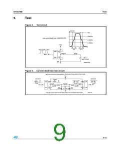
Figure 4.
Test circuit
OUTxY
Vcc
(3/4)Vcc
Low current dead time = MAX(DTr,DTf)
(1/2)Vcc
(1/4)Vcc
+Vcc
t
DTr
DTf
Duty cycle = 50%
INxY
M58
M57
OUTxY
R 8Ω
+
-
V67 =
vdc = Vcc/2
gnd
D03AU1458
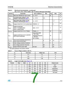
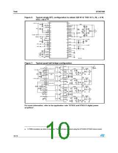
Figure 5.
Current dead time test circuit
High Current Dead time for Bridge application = ABS(DTout(A)-DTin(A))+ABS(DTOUT(B)-DTin(B))
+VCC
Duty cycle=A
Duty cycle=B
DTout(A)
M58
M57
M64
M63
Q1
OUTxA
Iout=4.5A
Q2
Q4
DTin(A)
INxA
DTout(B)
DTin(B)
INxB
Rload=8Ω
OUTxB
L67 22µ
L68 22µ
Iout=4.5A
Q3
C69
470nF
C70
470nF
C71 470nF
Duty cycle A and B: Fixed to have DC output current of 4.5A in the direction shown in figure
D00AU1162
9/13

 STMICROELECTRONICS [ ST ]