STA326
Volume loudness, preset volume curves, preset EQ settings, etc. New advanced AM radio inerference re-
duction modes.
The serial audio data input interface accepts all possible formats, including the popular I2S format.
Three channels of DDX® processing are provided. This high quality conversion from PCM audio to DDX's
patented tri-state PWM switching waveform provides over 100dB SNR and dynamic range.
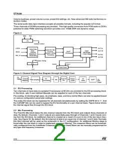
Figure 2.
SDA
SCL
I2C
System Control
LRCKI
BICKI
OUT1A
OUT1B
Serial Data
Input,
Channel
Mapping &
Resampling
Audio EQ, Mix,
Crossver,
Volume, Limiter
Quad
Half-Bridge
Power Stage
DDX®
Processing
OUT2A
OUT2B
Processing
SDI_12
EAPD
System Timing
PLL
CLK
TWARN
FAULT
Power-Down
Figure 3. Channel Signal Flow Diagram through the Digital Core
I2S
Input
Crossover
Filter
Channel
Mapping
EQ
Processing
Volume
Limiter
4X
Interp
DDX®
Re-sampling
Mix
DDX
Output
2.1 EQ Processing
Two channels of input data (re-sampled if necessary) at 96 kHz are provided to the EQ processing block.
In this block, upto 4 user-defined Biquads can be appplied to each of the two channels.
Pre-scaling, dc-blocking high-pass, de-emphasis, bass, and tone control filters can also be applied based
on various configuration parameter settings.
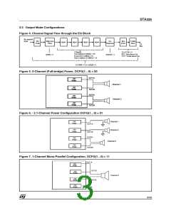
The entire EQ block can be bypassed for all channels simulatneously by setting the DSPB bit to '1'. And
the CxEQBP bits can be used to bypass the EQ functionality on a per channel basis. Figure below shows
the internal signal flow through the EQ block.
2.2 Mix Processing
The Post-EQ Mix block takes the two channel outputs from the EQ block and outputs three channels of
data. By default, Channels 1 and 2 outputs are essentially pass-through of Channels 1 and 2 inputs com-
ing from the EQ block. An additional channel is created as a result of a sum & mix of the two input chan-
nels. See Figure 30. By default, this 3rd channel of data is an equal mix of channel 1 and 2 data. Normally
this third channel will be used as the subwoofer in the 2.1 configuration. An additional filtering stage is
found after the mix block in order to implement crossover filtering. The crossover filters can be automati-
cally configured from the AutoMode Crossover (XO) bits or these filters can be manually programmed for
any type and frequency crossover.
2/43

 STMICROELECTRONICS [ ST ]