CONTROLLER AREA NETWORK (bxCAN)
10.10 CONTROLLER AREA NETWORK (bxCAN)
10.10.1 Introduction
■ 16-bit free running timer
■ Configurable timer resolution
■ Time Stamp sent in last two data bytes
Management
This peripheral Basic Extended CAN, named bx-
CAN, interfaces the CAN network. It supports the
CAN protocol version 2.0A and B. It has been de-
signed to manage a high number of incoming mes-
sages efficiently with a minimum CPU load. It also
meets the priority requirements for transmit mes-
sages.
■ Maskable interrupts
■ Software-efficient mailbox mapping at a unique
address space
For safety-critical applications, the CAN controller
provides all hardware functions for supporting the
CAN Time Triggered Communication option.
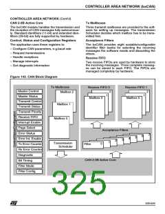
10.10.3 General Description
In today’s CAN applications, the number of nodes
in a network is increasing and often several net-
works are linked together via gateways. Typically
the number of messages in the system (and thus
to be handled by each node) has significantly in-
creased. In addition to the application messages,
Network Management and Diagnostic messages
have been introduced.
10.10.2 Main Features
■ Supports CAN protocol version 2.0 A, B Active
■ Bit rates up to 1Mbit/s
■ Supports the Time Triggered Communication
option
Transmission
– An enhanced filtering mechanism is required to
handle each type of message.
■ Three transmit mailboxes
■ Configurable transmit priority
■ Time Stamp on SOF transmission
Reception
■ Two receive FIFOs with three stages
■ Eight scalable filter banks
■ Identifier list feature
■ Configurable FIFO overrun
■ Time Stamp on SOF reception
Time Triggered Communication Option
■ Disable automatic retransmission mode
Furthermore, application tasks require more CPU
time, therefore real-time constraints caused by
message reception have to be reduced.
– A receive FIFO scheme allows the CPU to be
dedicated to application tasks for a long time pe-
riod without losing messages.
The standard HLP (Higher Layer Protocol) based
on standard CAN drivers requires an efficient in-
terface to the CAN controller.
– All mailboxes and registers are organized in 16-
byte pages mapped at the same address and se-
lected via a page select register.
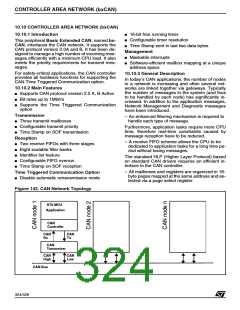
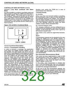
Figure 142. CAN Network Topology
ST9 MCU
Application
CAN
Controller
CAN
Rx
CAN
Tx
CAN
Transceiver
CAN
High
CAN
Low
CAN Bus
324/426
9

 STMICROELECTRONICS [ ST ]