J1850 Byte Level Protocol Decoder (JBLPD)
J1850 BYTE LEVEL PROTOCOL DECODER (Cont’d)
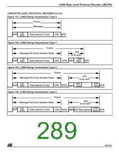
Transmitting a Type 2 IFR
is currently being received (See Figure 134). It
does so by writing the IFR3 or IFR3+CRC opcode
to the TXOP register. Transmitting IFR data type 3
is similar to transmitting a message, in that the TX-
DATA register is written with the first data byte fol-
lowed by a TXOP register write. For a single data
byte IFR3 transmission, the TXOP register would
be written with IFR3+CRC opcode set. The
MLC[3:0] bits can also be set to a proper value to
check for message length errors before enabling
the IFR transmit.
The user program will decide to transmit an IFR
type 2 byte in response to a message which is cur-
rently being received (See Figure 133). It does so
by writing the IFR2 opcode to the TXOP register.
Transmitting IFR data type 2 requires only a single
write of the TXOP register with the IFR2 opcode
set. The MLC[3:0] bits can also be set to check for
message length errors. If no error conditions (IBD,
IFD, TRA, RBRK or CRCE) exist to prevent trans-
mission, the JBLPD will transmit out the contents
of the PADDR register at the next EOD nominal
time period or after an EOD minimum time period if
a rising edge is detected on the filtered VPWI line
signifying another transmitter beginning early. The
NB1 symbol precedes the PADDR register value
and is followed with an EOF delimiter. The TRDY
flag will be cleared on the write of the TXOP regis-
ter. The TRDY bit is set once the NB1 begins
transmitting.
If no error conditions (IBD, IFD, TRA, RBRK or
CRCE) exist to prevent transmission, the JBLPD
will wait for an EOD nominal time period on the fil-
tered VPWI line (or for at least an EOD minimum
time followed by a rising edge signifying another
transmitter beginning early) at which time data is
transferred from the TXDATA register to the trans-
mit shift register. The TRDY bit is set since the TX-
DATA register is empty. A NB0 symbol is output
on the VPWO line followed by the data byte and
possibly the CRC byte if a IFR3+CRC opcode was
set. Once the first IFR3 byte has been successfully
transmitted, successive IFR3 bytes are sent with
TXDATA/TXOP write sequences where the
MLC[3:O] bits are don’t cares. The final byte in the
IFR3 string must be transmitted with the
IFR3+CRC opcode to trigger the JBLPD to ap-
pend the CRC byte to the string. The user program
may queue up the next message opcode se-
quence once the TRDY bit has been set.
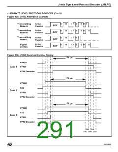
Lost arbitration for this case is a normal occur-
rence since type 2 IFR data is made up of single
bytes from multiple responders. If arbitration is lost
the VPWO line is released and the JBLPD waits
until the byte on the VPWI line is completed. Note
that the IFR that did make it out on the bus will be
received in the RXDATA register if it is not put into
sleep mode. Then, the JBLPD re-attempts to send
its physical address immediately after the end of
the last byte. The TLA bit is not set if arbitration is
lost and the user program does not need to re-
queue data or an opcode. The JBLPD will re-at-
tempt to send its PADDR register contents until it
successfully does so or the 12-byte frame maxi-
mum is reached if NFL=0. If NFL=1, then re-at-
tempts to send an lFR2 are executed until can-
celled by the CANCEL opcode or a JBLPD disa-
ble. Note that for the transmitter to synchronize to
the incoming signals of a frame, an IFR should be
queued before an EODM is received for the
present frame.
Although arbitration should never be lost for data
in the IFR portion of a type 3 frame, higher priority
messages are always honoured under the rules of
arbitration. If arbitration is lost then the block
should relinquish the bus by taking the VPWO line
to the passive state. In this case the TLA bit in the
STATUS register is set, and an interrupt will be
generated if enabled. Note also, that the IFR data
that did make it out on the bus will be received in
the RXDATA register if not in sleep mode. Note
that for the transmitter to synchronize to the in-
coming signals of a frame, an IFR should be
queued before an EODM is received for the cur-
rent frame.
Transmitting a Type 3 lFR Data String
The user program will decide to transmit an IFR
type 3 byte string in response to a message which
288/426
9

 STMICROELECTRONICS [ ST ]