SERIAL PERIPHERAL INTERFACE (SPI)
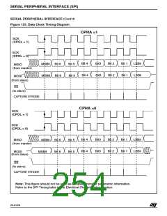
SERIAL PERIPHERAL INTERFACE (Cont’d)
10.7.5 Interrupt Management
Note: In the interrupt routine, reset the related
pending bit to avoid the interrupt request that was
just acknowledged being proposed again.
The interrupt of the Serial Peripheral Interface is
mapped on one of the eight External Interrupt
Channels of the microcontroller (refer to the “Inter-
rupts” chapter).
Then, after resetting the pending bit and before
the IRET instruction, check if the SPIF and MODF
interrupt flags in the SPSR register) are reset; oth-
erwise jump to the beginning of the routine. If, on
return from an interrupt routine, the pending bit is
reset while one of the interrupt flags is set, no in-
terrupt is performed on that channel until the flags
are set. A new interrupt request is performed only
when a flag is set with the other not set.
Each External Interrupt Channel has:
– A trigger control bit in the EITR register (R242 -
Page 0),
– A pending bit in the EIPR register (R243 -
Page0),
– A mask bit in the EIMR register (R244 - Page 0).
10.7.5.1 Register Map
Program the interrupt priority level using the EI-
PLR register (R245 - Page 0). For a description of
these registers refer to the “Interrupts” and “DMA”
chapters.
Depending on the device, one or two Serial Pe-
ripheral interfaces can be present. The previous
table summarizes the position of the registers of
the two peripherals in the register map of the mi-
crocontroller.
To use the interrupt feature, perform the following
sequence:
Address
Page
Name
DR0
CR0
SR0
PR0
DR1
CR1
SR1
PR1
– Set the priority level of the interrupt channel used
for the SPI (EIPRL register)
SPI0
R240 (F0h)
R241 (F1h)
R242 (F2h)
R243 (F3h)
R248 (F8h)
R249 (F9h)
R250 (FAh)
R251 (FBh)
7
7
7
7
7
7
7
7
– Select the interrupt trigger edge as rising edge
(set the corresponding bit in the EITR register)
– Set the SPIS bit of the SPCR register to select
the peripheral interrupt source
– Set the SPIE bit of the SPCR register to enable
the peripheral to perform interrupt requests
SPI1
– In the EIPR register, reset the pending bit of the
interrupt channel used by the SPI interrupt to
avoid any spurious interrupt requests being per-
formed when the mask bit is set
– Set the mask bit of the interrupt channel used to
enable the MCU to acknowledge the interrupt re-
quests of the peripheral.
258/426
9

 STMICROELECTRONICS [ ST ]