ST92F124/F150/F250 - INTERRUPTS
WAKE-UP / INTERRUPT LINES MANAGEMENT UNIT (Cont’d)
5.12.5 Register Description
low, the ST9 will enter STOP mode independently
of the status of the STOP bit.
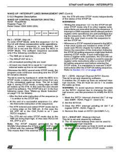
WAKE-UP CONTROL REGISTER (WUCTRL)
R249 - Read/Write
Register Page: 57
Reset Value: 0000 0000 (00h)
WARNINGS:
– Writing the sequence 1,0,1 to the STOP bit will
enter STOP mode only if no other register write
instructions are executed during the sequence. If
Interrupt or DMA requests (which always perform
register write operations) are acknowledged dur-
ing the sequence, the ST9 will not enter STOP
mode: the user must re-enter the sequence to
set the STOP bit.
7
0
-
-
-
-
-
STOP ID1S WKUP-INT
Bit 2 = STOP: Stop bit.
To enter STOP Mode, write the sequence 1,0,1 to
this bit with three consecutive write operations.
When a correct sequence is recognized, the
STOP bit is set and the RCCU puts the MCU in
STOP Mode. The software sequence succeeds
only if the following conditions are true:
– Whenever a STOP request is issued to the MCU,
a few clock cycles are needed to enter STOP
mode (see RCCU chapter for further details).
Hence the execution of the instruction following
the STOP bit setting sequence might start before
entering STOP mode: if such instruction per-
forms a register write operation, the ST9 will not
enter in STOP mode. In order to avoid to execute
register write instructions after a correct STOP
bit setting sequence and before entering the
STOP mode, it is mandatory to execute 3 NOP
instructions after the STOP bit setting sequence.
Refer to Section 13.1.2 on page 408.
– The NMI pin is kept low,
– The WKUP-INT bit is 1,
– All unmasked pending bits are reset
– At least one mask bit is equal to 1 (at least one
external wake-up line is not masked).
Otherwise the MCU cannot enter STOP mode, the
program code continues executing and the STOP
bit remains cleared.
Bit 1 = ID1S: Interrupt Channel INTD1 Source.
This bit is set and cleared by software.
It enables the 16 wake-up lines as external inter-
rupt sources. This bit must be set to 1 to enable
the wake-up lines.
The bit is reset by hardware if, while the MCU is in
STOP mode, a wake-up interrupt comes from any
of the unmasked wake-up lines. The bit is kept
high if, during STOP mode, a rising edge on NMI
pin wakes up the ST9. In this case the user should
reset it by software. The STOP bit is at 1 in the four
following cases (See “Wake-up Mode Selection”
on page 113. for details):
WARNING: To avoid spurious interrupt requests
on the INTD1 channel due to changing the inter-
rupt source, use this procedure to modify the ID1S
bit:
– After the first write instruction of the sequence (a
1 is written to the STOP bit)
1. Mask the INTD1 interrupt channel (bit 7 of reg-
ister EIMR - R244, Page 0 - reset to 0).
– At the end of a successful sequence (i.e. after
the third write instruction of the sequence)
2. Set the ID1S bit.
3. Clear the IPD1 interrupt pending bit (bit 7 of
register EIPR - R243, Page 0)
– The ST9 entered and exited STOP mode due to
a rising edge on the NMI pin. In this case the
EX_STP bit in the CLK_FLAG is at 1 (see
RCCU chapter).
4. Remove the mask on INTD1 (bit EIMR.7=1).
– The ST9 did not enter STOP mode due to the
NMI pin being kept high. In this case RCCU bit
EX_STP is at 0
Bit 0 = WKUP-INT: Wakeup Interrupt.
This bit is set and cleared by software.
0: The 16 external wakeup lines can be used to
generate interrupt requests
1: The 16 external wake-up lines to work as wake-
up sources for exiting from STOP mode
Note: The STOP request generated by the
WUIMU (that allows the ST9 to enter STOP mode)
is ORed with the external STOP pin (active low).
This means that if the external STOP pin is forced
117/426
9

 STMICROELECTRONICS [ ST ]