ST92F124/F150/F250 - INTERRUPTS
INTERRUPT REGISTERS (Cont’d)
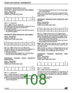
INTERRUPT PENDING REGISTER LOW
(SIPRL)
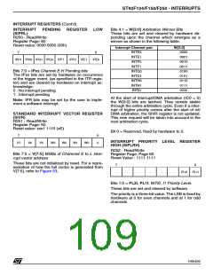
Bits 4:1 = W[3:0] Arbitration Winner Bits
These bits are set and cleared by hardware de-
pending upon the channel which emerges as a
winner as shown in the following table.
R250 - Read/Write
Register Page: 60
Reset value: 0000 0000 (00h)
Interrupt Channel pair
INTE0
W[3:0]
0000
7
0
INTE1
0001
0010
0011
0100
0101
0110
0111
1000
IPH1 IPH0 IPG1 IPG0
IPF1
IPF0
IPE1
IPE0
INTF0
INTF1
Bits 7:0 = IPxx Channel E-H Pending bits
INTG0
The IPxx bits are set by hardware on occurrence
of the trigger event. (as specified in the ITR regis-
ter) and are cleared by hardware on interrupt ac-
knowledge.
INTG1
INTH0
INTH1
INTI0
0 : No interrupt pending
1 : Interrupt pending
At the start of interrupt/DMA arbitration (IC0 = 0)
the W[3:0] bits are latched. They remain stable
through the entire arbitration cycle. Even if a inter-
rupt of higher priority comes after the start of int/
DMA arbitration, the SIVR register is not updated.
This new request will be taken into account in the
next arbitration cycle.
Note: IPR bits may be set by the user to imple-
ment a software interrupt.
STANDARD INTERRUPT VECTOR REGISTER
(SIVR)
R251 - Read/Write
Register Page: 60
Reset value: xxx1 1110 (xE)
Bit 0 = Reserved, fixed by hardware to 0.
7
0
0
INTERRUPT PRIORITY LEVEL REGISTER
HIGH (SIPLRH)
V7
V6
V5
W3
W2
W1
W0
R252 - Read/Write
Register Page: Page 60
Reset Value : 1111 1111
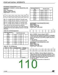
Bits 7:5 = V[7:5] MSBs of Channnel E to L inter-
rupt vector address
These bits are not initialized by reset. For a repre-
sentation of how the full vector is generated from
V[7:5], refer to Figure 53.
7
-
0
-
-
-
-
-
PL2I
PL1I
Bits 1:0 = PL2I, PL1I: INTI0, I1 Priority Level.
These bits are set and cleared by software.
The priority is a three-bit value. The LSB is fixed by
hardware at 0 for even channels and at 1 for odd
channels
109/426
9

 STMICROELECTRONICS [ ST ]