Bootstrap loader
ST10F276E
5.6.12
Example
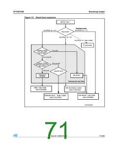
In the following example, Alternate Boot Mode works as follows:
On rising edge of RSTIN pin, the reset configuration is latched.
–
●
●
●
If Bootstrap Loader mode is not enabled (P0L[5..4] = ‘11’), ST10F276E hardware
proceeds with a standard hardware reset procedure.
If standard Bootstrap Loader is enabled (P0L[5..4] = ‘10’), the standard ST10 Bootstrap
Loader is enabled and a variable is cleared to indicate that ABM is not enabled.
If Alternate Boot Mode is selected (P0L[5..4] = ‘01’), then, depending on signatures
integrity checks, a predefined reset sequence is activated.
5.7
Selective boot mode
The selective boot is a subcase of the Alternate Boot Mode. When none of the signatures
are correct, instead of executing the standard bootstrap loader (triggered by P0L.4 low at
reset), an additional check is made.
Address 00’1FFCh is read again with the following behavior:
●
If value is 0000h or FFFFh, a jump is performed to the standard bootstrap loader.
Otherwise:
●
–
–
High byte is disregarded.
Low byte bits select which communication channel is enabled.
Table 37. Selective boot
Bit
Function
UART selection
0
0: UART is not watched for a Start condition.
1: UART is watched for a Start condition.
CAN1 selection
1
0: CAN1 is not watched for a Start condition.
1: CAN1 is watched for a Start condition.
Reserved
2..7
For upward compatibility, must be programmed to ‘0’
Therefore a value:
●
●
●
0xXX03 configures the Selective Bootstrap Loader to poll for RxD0 and CAN1_RxD.
0xXX01 configures the Selective Bootstrap Loader to poll only RxD0 (no boot via CAN).
0xXX02 configures the Selective Bootstrap Loader to poll only CAN1_RxD (no boot via
UART).
●
Other values allow the ST10F276E to execute an endless loop into the Test-Flash.
70/235
Doc ID 12303 Rev 3

 STMICROELECTRONICS [ ST ]