Central processing unit (CPU)
ST10F276E
6
Central processing unit (CPU)
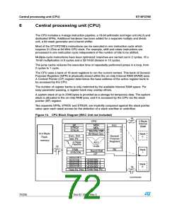
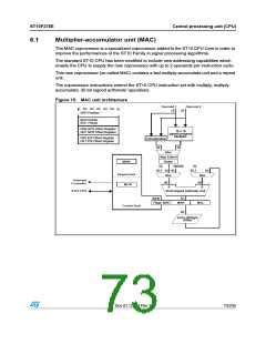
The CPU includes a 4-stage instruction pipeline, a 16-bit arithmetic and logic unit (ALU) and
dedicated SFRs. Additional hardware has been added for a separate multiply and divide
unit, a bit-mask generator and a barrel shifter.
Most of the ST10F276E’s instructions can be executed in one instruction cycle which
requires 31.25ns at 64 MHz CPU clock. For example, shift and rotate instructions are
processed in one instruction cycle independent of the number of bits to be shifted.
Multiple-cycle instructions have been optimized: branches are carried out in 2 cycles, 16 x
16-bit multiplication in 5 cycles and a 32/16-bit division in 10 cycles.
The jump cache reduces the execution time of repeatedly performed jumps in a loop, from
2 cycles to 1 cycle.
The CPU uses a bank of 16 word registers to run the current context. This bank of General
Purpose Registers (GPR) is physically stored within the on-chip Internal RAM (IRAM) area.
A Context Pointer (CP) register determines the base address of the active register bank to
be accessed by the CPU.
The number of register banks is only restricted by the available Internal RAM space. For
easy parameter passing, a register bank may overlap others.
A system stack of up to 2048 bytes is provided as a storage for temporary data. The system
stack is allocated in the on-chip RAM area, and it is accessed by the CPU via the stack
pointer (SP) register.
Two separate SFRs, STKOV and STKUN, are implicitly compared against the stack pointer
value upon each stack access for the detection of a stack overflow or underflow.
Figure 14. CPU Block Diagram (MAC Unit not included)
ꢀꢄ
#05
-$(
ꢁ +BYTE
)NTERNAL
2!-
30
34+/6
2ꢀꢃ
-$,
34+5.
-ULꢌꢂ$IVꢌꢅ(7
"ITꢅ-ASK 'ENꢌ
ꢃꢀꢁ +BYTE
&LASH
"ANK
N
%XECꢌ 5NIT
)NSTRꢌ 0TR
'ENERAL
0URPOSE
2EGISTERS
MEMORY
ꢇꢅ3TAGE
0IPELINE
!,5
ꢀꢄꢅ"IT
ꢈꢁ
2ꢉ
037
393#/.
"ANK
I
"ARRELꢅ3HIFT
#0
"53#/. ꢉ
!$$23%, ꢀ
!$$23%, ꢁ
!$$23%, ꢈ
"53#/. ꢀ
"53#/. ꢁ
"53#/. ꢈ
"53#/. ꢇ
"ANK
ꢉ
!$$23%, ꢇ
ꢀꢄ
#ODE 3EGꢌ 0TRꢌ
$ATA 0Gꢌ 0TRS
'!0'2)ꢉꢉꢈꢈꢉ
72/235
Doc ID 12303 Rev 3

 STMICROELECTRONICS [ ST ]