ST10F276E
Bootstrap loader
5.6
Alternate boot mode (ABM)
5.6.1
Activation
Alternate boot is activated with the combination ‘01’ on Port0L[5..4] at the rising edge of
RSTIN.
5.6.2
Memory mapping
The ST10F276E has the same memory mapping for standard boot mode and for alternate
boot mode:
●
Test-Flash: Mapped from 00’0000h. The Standard Bootstrap Loader can be started by
executing a jump to the address of this routine (JMPS 00’xxxx; address to be defined).
●
User Flash: The User Flash is divided in two parts: The IFLASH, visible only for
memory reads and memory writes (no code fetch) and the XFLASH, visible for any
ST10 access (memory read, memory write and code fetch).
●
All ST10F276E XRAM and Xperipherals modules can be accessed if enabled in
XPERCON register.
Note:
The alternate boot mode can be used to reprogram the whole content of the ST10F276E
User Flash (except Block 0 in Bank 2, where the alternate boot is mapped into).
5.6.3
Interrupts
The ST10 interrupt vector table is always mapped from address 00’0000h.
As a consequence, interrupts are not allowed in Alternate Boot Mode; all maskable and non-
maskable interrupts must be disabled.
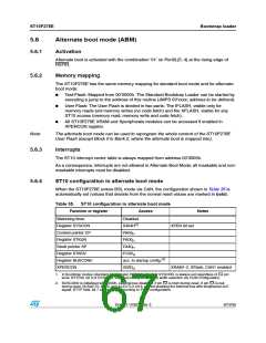
5.6.4
ST10 configuration in alternate boot mode
When the ST10F276E enters BSL mode via CAN, the configuration shown in Table 35 is
automatically set (values that deviate from the normal reset values are marked in bold).
Table 35. ST10 configuration in alternate boot mode
Function or register
Watchdog timer
Access
Notes
Disabled
0404H(1)
FA00H
Register SYSCON
Context pointer CP
Register STKUN
Stack pointer SP
Register STKOV
Register BUSCON0
XPERCON
XPEN bit set
FA00H
FA40H
FC00H
acc. to startup config.(2)
002DH
XRAM1-2, XFlash, CAN1 enabled
1. In Bootstrap modes (standard or alternate) ROMEN, bit 10 of SYSCON, is always set regardless of EA pin
level. BYTDIS, bit 9 of SYSCON, is set according to data bus width selection via Port0 configuration.
2. BUSCON0 is initialized with 0000h, external bus disabled, if pin EA is high during reset. If pin EA is low
during reset, BUSACT0, bit 10, and ALECTL0, bit 9, are set enabling the external bus with lengthened ALE
signal. BTYP field, bit 7 and 6, is set according to Port0 configuration.
Doc ID 12303 Rev 3
67/235

 STMICROELECTRONICS [ ST ]