ST10F276E
Bootstrap loader
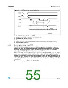
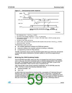
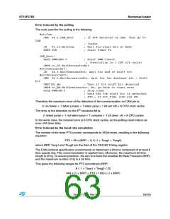
Figure 11. CAN bootstrap loader sequence
234).
0ꢉ,ꢌꢇ
ꢍꢀꢏ
ꢁ
ꢍꢇꢏ
#!.ꢀ?2X$
ꢍꢈꢏ
#!.ꢀ?4X$
ꢍꢃꢏ
#30ꢐ)0
ꢀꢁꢆ BYTES
USER SOFTWARE
ꢍꢄꢏ )NTꢌ "OOT 2/- ꢂ 4ESTꢅ&LASH "3,ꢅROUTINE
'!0'2)ꢉꢉꢈꢁꢊ
1. BSL initialization time, > 1ms @ f
= 40 MHz
CPU
2. Zero frame (CAN message: standard ID = 0, DLC = 0), sent by host
3. CAN message (standard ID = E6h, DLC = 3, Data0 = D5h, Data1-Data2 = IDCHIP_low-high), sent by
ST10F276E on request
4. 128 bytes of code / data, sent by host
5. Caution: CAN1_TxD is only driven a certain time after reception of the zero byte (1.3ms @ f
6. Internal Boot ROM / Test-Flash
= 40 MHz).
CPU
The Bootstrap Loader can load
●
●
●
the complete application software into ROM-less systems,
temporary software into complete systems for testing or calibration,
a programming routine for Flash devices.
The BSL mechanism may be used for standard system start-up as well as for only special
occasions like system maintenance (firmware update) or end-of-line programming or
testing.
5.4.2
Entering the CAN bootstrap loader
The ST10F276E enters BSL mode if pin P0L.4 is sampled low at the end of a hardware
reset. In this case, the built-in bootstrap loader is activated independently of the selected
bus mode. The bootstrap loader code is stored in a special Test-Flash; no part of the
standard mask ROM or Flash memory area is required for this.
After entering BSL mode and the respective initialization, the ST10F276E scans the
CAN1_TxD line to receive the following initialization frame:
●
Standard identifier = 0h
DLC = 0h
●
As all the bits to be transmitted are dominant bits, a succession of 5 dominant bits and 1
stuff bit on the CAN network is used. From the duration of this frame, it calculates the
corresponding baud rate factor with respect to the current CPU clock, initializes the CAN1
interface accordingly, switches pin CAN1_TxD to output and enables the CAN1 interface to
take part in the network communication. Using this baud rate, a Message Object is
Doc ID 12303 Rev 3
59/235

 STMICROELECTRONICS [ ST ]