Bootstrap loader
ST10F276E
bootstrap loading sequence is now terminated; however, the ST10F276E remains in BSL
mode. Most probably the initially loaded routine will load additional code or data, as an
average application is likely to require substantially more than 64 instructions. This second
receive loop may directly use the pre-initialized CAN interface to receive data and store it in
arbitrary user-defined locations.
This second level of loaded code may be
●
the final application code
●
another, more sophisticated, loader routine that adds a transmission protocol to
enhance the integrity of the loaded code or data
●
a code sequence to change the system configuration and enable the bus interface to
store the received data into external memory
This process may go through several iterations or may directly execute the final application.
In all cases the ST10F276E still runs in BSL mode, that is, with the watchdog timer disabled
and limited access to the internal Flash area. All code fetches from the internal Flash area
(01’0000H ...08’FFFFH) are redirected to the special Test-Flash. Data read operations will
access the internal Flash of the ST10F276E.
5.4.5
Choosing the baud rate for the BSL via CAN
The Bootstrap via CAN acts the same way as in the UART bootstrap mode. When the
ST10F276E is started in BSL mode, it polls the RxD0 and CAN1_RxD lines. When polling a
low level on one of these lines, a timer is launched that is stopped when the line returns to
high level.
For CAN communication, the algorithm is made to receive a zero frame, that is, the standard
identifier is 0x0, DLC is 0. This frame produces the following levels on the network: 5D, 1R,
5D, 1R, 5D, 1R, 5D, 1R, 5D, 1R, 4D, 1R, 1D, 11R. The algorithm lets the timer run until the
detection of the 5th recessive bit. This way the bit timing is calculated over the duration of 29
bit times: This minimizes the error introduced by the polling.
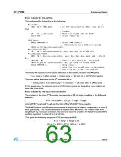
Figure 12. Bit rate measurement over a predefined zero-frame
3TART
3TUFF BIT
3TUFF BIT
3TUFF BIT
3TUFF BIT
ꢌꢌꢌꢌꢌꢌꢌꢌ
-EASURED TIME
'!0'2)ꢉꢉꢈꢁꢆ
62/235
Doc ID 12303 Rev 3

 STMICROELECTRONICS [ ST ]