Internal Flash memory
ST10F276E
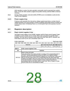
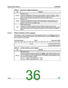
4.3.4
Flash control register 1 high
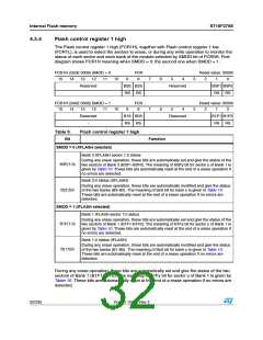
The Flash control register 1 high (FCR1H), together with Flash control register 1 low
(FCR1L), is used to select the sectors to erase, or during any write operation to monitor the
status of each sector and each bank of the module selected by SMOD bit of FCR0H. First
diagram shows FCR1H meaning when SMOD = 0; the second one when SMOD = 1.
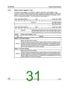
FCR1H (0x0E 0006) SMOD = 0
15 14 13 12 11
Reserved
FCR
8
Reset value: 0000h
10
10
9
7
7
6
6
5
4
3
3
2
1
0
B3S B2S
RS RS
Reserved
B3F1 B3F0
RS RS
FCR1H (0x0E 0006) SMOD = 1
15 14 13 12 11
FCR
Reset value: 0000h
9
8
5
4
2
1
0
Reserved
-
B1S B0S
RS RS
Reserved
B1F1 B1F0
RS RS
Table 9.
Bit
Flash control register 1 high
Function
SMOD = 0 (XFLASH selected)
Bank 3 XFLASH sector 1:0 status
During any erase operation, these bits are automatically set and give the status of the
two sectors of Bank 3 (B3F1-B3F0). The meaning of B3Fy bit for sector y of Bank 1 is
given by Table 10. These bits are automatically reset at the end of a erase operation if
no errors are detected.
B3F(1:0)
B(3:2)S
Bank 3-2 status (XFLASH)
During any erase operation, these bits are automatically modified and give the status
of the two banks (B3-B2). The meaning of BxS bit for bank x is given in Table 10.
These bits are automatically reset at the end of a erase operation if no errors are
detected.
SMOD = 1 (IFLASH selected)
Bank 1 IFLASH sector 1:0 status
During any erase operation, these bits are automatically set and give the status of the
two sectors of Bank 1 (B1F1-B1F0). The meaning of B1Fy bit for sector y of Bank 1 is
given by Table 10. These bits are automatically reset at the end of a erase operation if
no errors are detected.
B1F(1:0)
B(1:0)S
Bank 1-0 status (IFLASH)
During any erase operation, these bits are automatically modified and give the status
of the two banks (B1-B0). The meaning of BxS bit for bank x is given in Table 10.
These bits are automatically reset at the end of a erase operation if no errors are
detected.
During any erase operation, these bits are automatically set and give the status of the two
sectors of Bank 1 (B1F1-B1F0). The meaning of B1Fy bit for sector y of Bank 1 is given by
Table 10. These bits are automatically reset at the end of a erase operation if no errors are
detected.
32/235
Doc ID 12303 Rev 3

 STMICROELECTRONICS [ ST ]