Programming manual
powerSTEP01
Any attempt to write to the register, when the motor is running, causes the command to be
ignored and the CMD_ERROR to rise (see Section 11.1.28).
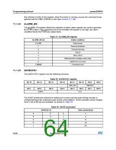
11.1.24 ALARM_EN
The ALARM_EN register allows the selection of which alarm signals are used to generate
the FLAG output. If the respective bit of the ALARM_EN register is set high, the alarm
condition forces the FLAG pin output down.
Table 31. ALARM_EN register
ALARM_EN bit
Alarm condition
0 (LSB)
Overcurrent
Thermal shutdown
Thermal warning
UVLO
1
2
3
4
ADC UVLO
5
6
Stall detection (voltage mode only)
Switch turn-on event
Command error
7 (MSB)
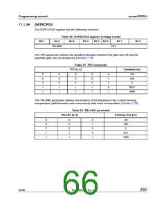
11.1.25 GATECFG1
The GATECFG1 register has the following structure:
Table 32. GATECFG1 register
Bit 15
Bit 7
Bit 14
Bit 13
Bit 5
Bit 12
Bit 4
Bit 11
Bit 10
Bit 9
Bit 8
Bit 0
WD_EN
TBOOST
Bit 6
Bit 3
Bit 2
Bit 1
IGATE
TCC
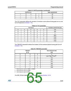
The IGATE parameter selects the sink/source current used by gate driving circuitry to
charge/discharge the respective gate during commutations. Seven possible values ranging
from 4 mA to 96 mA are available, as shown in Table 33.
Table 33. IGATE parameter
IGATE [2..0}
Gate current [mA}
0
0
0
0
1
0
0
1
1
0
0
1
0
1
0
4
4
8
16
24
64/90
DocID025022 Rev 1

 STMICROELECTRONICS [ ST ]