Programming manual
powerSTEP01
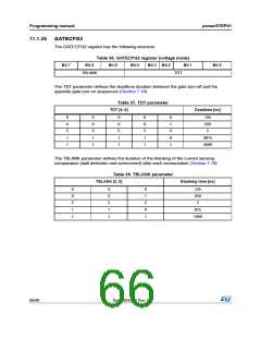
11.1.26 GATECFG2
The GATECFG2 register has the following structure:
Table 36. GATECFG2 register (voltage mode)
Bit 5 Bit 4 Bit 3 Bit 2 Bit 1
Bit 7
Bit 6
Bit 0
TBLANK
TDT
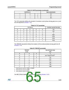
The TDT parameter defines the deadtime duration between the gate turn-off and the
opposite gate turn-on sequences (Section 7.16).
Table 37. TDT parameter
TDT [4..0]
Deadtime [ns]
0
0
1
1
0
0
1
1
0
0
1
1
0
0
1
1
0
1
0
1
125
250
3875
4000
The TBLANK parameter defines the duration of the blanking of the current sensing
comparators (stall detection and overcurrent) after each commutation (Section 7.16).
Table 38. TBLANK parameter
TBLANK [2..0]
Blanking time [ns]
0
0
1
1
0
0
1
1
0
1
0
1
125
250
875
1000
66/90
DocID025022 Rev 1

 STMICROELECTRONICS [ ST ]