powerSTEP01
Programming manual
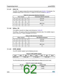
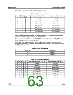
STEP_SEL selects one of eight possible stepping modes:
Table 28. Step mode selection
Step mode (CM_VM = 0)
STEP_SEL[2..0]
Step mode (CM_VM = 1)
0
0
0
0
1
1
1
1
0
0
1
1
0
0
1
1
0
1
0
1
0
1
0
1
Full-step
Full-step
Half-step
Half-step
1/4 microstep
1/8 microstep
1/16 microstep
1/32 microstep
1/64 microstep
1/128 microstep
1/4 microstep
1/8 microstep
1/16 microstep
1/16 microstep
1/16 microstep
1/16 microstep
Every time the step mode changes, the electrical position (i.e. the point of microstepping
sinewave that is generated) resets at the first microstep.
It is important to note that every time STEP_SEL changes, the value in ABS_POS register
loses meaning and then it should be reset.
When sync clock is disabled, BUSY/SYNC output is used as dSpin (command state
machine busy signaling), otherwise BUSY/SYNC output provides a clock signal according
to SYNC_SEL parameter.
Table 29. Sync clock enable
SYNC_EN
Sync clock
0
1
Disabled
Enabled
Table 30. Sync clock selection
SYNC_SEL[2..0]
Step information (CM_VM = 0)
Step information (CM_VM = 1)
0
0
0
0
1
1
1
1
0
0
1
1
0
0
1
1
0
1
0
1
0
1
0
1
Full-step
Full-step
Half-step
Half-step
1/4 microstep
1/8 microstep
1/16 microstep
1/32 microstep
1/64 microstep
1/128 microstep
1/4 microstep
1/8 microstep
1/16 microstep
Always low
Always low
Always low
DocID025022 Rev 1
63/90

 STMICROELECTRONICS [ ST ]