powerSTEP01
Phase current control: current mode
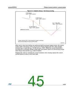
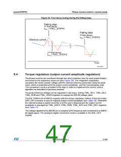
Figure 23. Fast decay tuning during the falling steps
Falling step
st
1 fast decay:
tFALL = FALL_STEP/4
Falling step
st
1 fast decay:
tFALL= FALL_STEP/2
reference current
2nd fast decay:
FALL= FALL_STEP/2
t
Time
AM15052v1
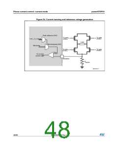
9.4
Torque regulation (output current amplitude regulation)
The phase currents are monitored through two shunt resistors (one for each power bridge)
connected to the respective sense pin (see Figure 24). The integrated comparator
compares the sense resistor voltage with the internal reference generated using the peak
value, which is proportional to the output current amplitude, and the microstepping code.
The comparison result is provided to the logic in order to implement the current control
algorithm as described in previous sections.
The peak reference voltage can be regulated in two ways: writing TVAL_ACC, TVAL_DEC,
TVAL_RUN and TVAL_HOLD registers or varying the ADCIN voltage value.
The EN_TQREG bit (CONFIG register) sets the torque regulation method. If this bit is high,
ADC_OUT prevalue is used to regulate output current amplitude (see Table 23). Otherwise
the internal analog-to-digital converter is at the user’s disposal and the output current
amplitude is managed by TVAL_HOLD, TVAL_RUN, TVAL_ACC and TVAL_DEC registers
(see Table 17).
The voltage applied to the ADCIN pin is sampled at fS frequency and converted in an NADC
bit digital signal. The analog-to-digital conversion result is available in the ADC_OUT
register.
DocID025022 Rev 1
47/90

 STMICROELECTRONICS [ ST ]