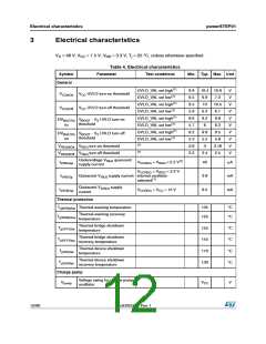
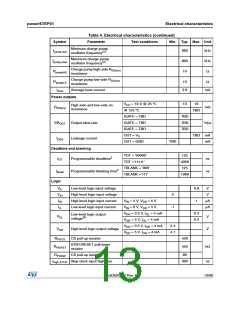
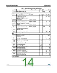
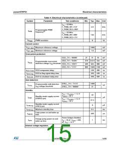
Electrical characteristics
Symbol
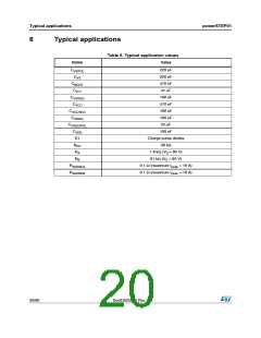
powerSTEP01
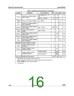
Table 4. Electrical characteristics (continued)
Parameter
Test conditions
Min. Typ. Max. Unit
Low (default), ICC = 10
mA
7.3
14
7.5
15
V
Internal VCC voltage regulator
output voltage
VCCOUT
High, ICC = 10 mA
ICC = 50 mA
VSREG,
VSREG to VCC dropout voltage
3
V
W
drop
Internal VCC voltage regulator
power dissipation
PCC
2.5
Internal VREG voltage regulator
output voltage
VREGOUT
IREG = 10 mA
IREG = 50 mA
3.135 3.3
V
VCCREG, VCCREG to VREG dropout
3
V
voltage
drop
Internal VREG voltage regulator
output current
IREGOUT
125
55
mA
mA
W
IREGOUT,S Internal VREG voltage regulator
output standby current
TBY
Internal VREG voltage regulator
power dissipation
PREG
0.5
Integrated analog to digital converter
Analog to digital converter
resolution
NADC
5
bit
Analog to digital converter
VADC,ref
3.3
V
reference voltage
Voltage mode(2)
Current mode(2)
fPWM
kHz
kHz
V
Analog to digital converter
sampling frequency
fS
fOSC
/512
VADC,UVLO ADCIN UVLO threshold
1.05 1.16 1.35
1. Guaranteed in the temperature range -25 to 125 °C.
2. The value accuracy is dependent on oscillator frequency accuracy (Section 7.8).
3. FLAG and BUSY open-drain outputs included.
4. See Figure 25.
16/90
DocID025022 Rev 1

 STMICROELECTRONICS [ ST ]