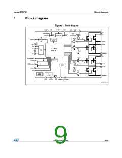
powerSTEP01
Electrical characteristics
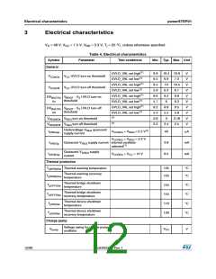
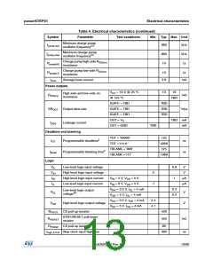
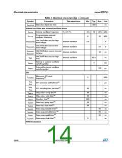
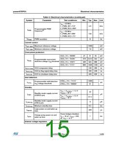
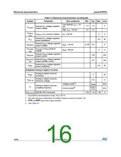
Table 4. Electrical characteristics (continued)
Symbol
Parameter
Test conditions
Min. Typ. Max. Unit
Minimum charge pump
oscillator frequency(2)
fpump,min
fpump,max
RpumpHS
660
800
10
kHz
kHz
Ω
Maximum charge pump
oscillator frequency(2)
Charge pump high-side RDS(on)
resistance
Charge pump low-side RDS(on)
resistance
RpumpLS
Iboot
10
Ω
Average boot current
2.6
mA
Power outputs
VCC = 10 V @ 25 °C
@ 125 °C
13
16
High-side and low-side on-
resistance
RDS(on)
mΩ
TBD
IGATE = TBD
IGATE = TBD
IGATE = TBD
OUT = VS
TBD
TBD
TBD
SROUT Output slew-rate
V/μs
TBD mA
mA
IDSS
Leakage current
OUT = GND
TBD
Deadtime and blanking
TDT = '00000'
TDT =’11111’
125
4000
125
tDT
Programmable deadtime2
ns
ns
TBLANK = '000'
TBLANK =’111’
tblank
Programmable blanking time2
1000
Logic
VIL
VIH
IIH
Low level logic input voltage
High level logic input voltage
High level logic input current
Low level logic input current
0.8
1
V
V
2
VIN = 5 V, VDD = 5 V
VIN = 0 V, VDD = 5 V
VDD = 3.3 V, IOL = 4 mA
VDD = 5 V, IOL = 4 mA
μA
μA
IIL
-1
0.3
0.3
Low level logic output
voltage(3)
VOL
V
V
V
DD = 3.3 V, IOH = 4 mA
2.4
4.7
VOH
High level logic output voltage
CS pull-up resistor
VDD = 5 V, IOH = 4 mA
RPUCS
430
450
STBY/RESET pull-down
resistor
RPDRST
kΩ
ns
RPUSW CS pull-up resistor
80
thigh,STCK Step-clock input high time
300
DocID025022 Rev 1
13/90

 STMICROELECTRONICS [ ST ]