powerSTEP01
Electrical characteristics
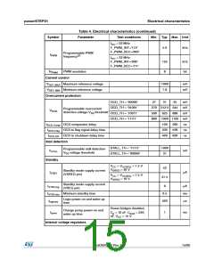
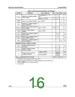
Table 4. Electrical characteristics (continued)
Symbol
Parameter
Test conditions
Min. Typ. Max. Unit
fosc = 32 MHz
F_PWM_INT=’11X’
F_PWM_DEC=’000’
5.6
kHz
Programmable PWM
frequency(2)
fPWM
fosc = 32 MHz
F_PWM_INT=’000’
F_PWM_DEC=’111’
125
8
kHz
bit
NPWM
PWM resolution
Current control
VREF, MAX Maximum reference voltage
VREF, MIN Minimum reference voltage
1000
7.8
mV
mV
Overcurrent protection
OCD_TH = ‘00000’
OCD_TH = ‘01001’
OCD_TH = ‘10011’
OCD_TH = '11111'
27
31
35
mV
mV
mV
270 312.5 344
500 625 688
Programmable overcurrent
VOCD
detection voltage VDS threshold
800 1000 1100 mV
tOCD,Comp OCD comparator delay
tOCD,Flag OCD to flag signal delay time
tOCD,SD OCD to shutdown delay time
100
230
400
200
530
630
ns
ns
ns
Stall detection
STALL_TH = '11111'
STALL_TH = '00000'
1000
31
Programmable stall detection
VDS voltage threshold
V
mV
STALL
Standby
VCC = VCCREG = 7.5 V
42
V
SREG = 48 V
Standby mode supply current
(VSREG pin)
ISTBY
μA
VCC = VCCREG = 7.5 V
VSREG = 18 V
37.5
Standby mode supply current
(VREG pin)
ISTBY,reg
6
μA
ms
μs
tSTBY,min Minimum standby time
0.5
500
Logic power-on and wake-up
tlogicwu
time
Power bridges disabled,
Cp = 10 nF, Cboot = 220
nF, VCC = 15 V
Charge pump power-on and
wake-up time
tcpwu
1
ms
Internal voltage regulators
DocID025022 Rev 1
15/90

 STMICROELECTRONICS [ ST ]