M41T00
M41T00 clock operation
(1)
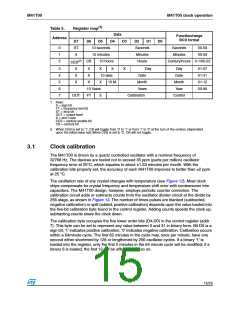
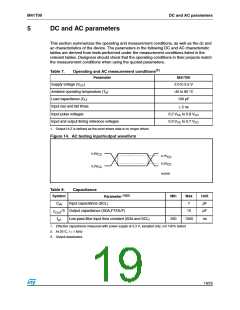
Table 5.
Address
Register map
Data
D4
Function/range
BCD format
D7
ST
X
D6
D5
D3
D2
D1
D0
0
1
2
10 seconds
10 minutes
Seconds
Minutes
Hours
Seconds
Minutes
00-59
00-59
CEB(2)
CB
10 hours
Century/hours 0-1/00-23
3
X
X
X
X
X
X
X
X
X
Day
Day
Date
01-07
01-31
01-12
00-99
4
10 date
10 M.
Date
Month
5
X
Month
Year
6
7
10 Years
FT
Years
OUT
S
Calibration
Control
1. Keys:
S = sign bit
FT = frequency test bit
ST = stop bit
OUT = output level
X = don’t care
CEB = century enable bit
CB = century bit
2. When CEB is set to '1', CB will toggle from '0' to '1' or from '1' to '0' at the turn of the century (dependent
upon the initial value set).When CEB is set to '0', CB will not toggle.
3.1
Clock calibration
The M41T00 is driven by a quartz controlled oscillator with a nominal frequency of
32768 Hz. The devices are tested not to exceed 35 ppm (parts per million) oscillator
frequency error at 25°C, which equates to about 1.53 minutes per month. With the
calibration bits properly set, the accuracy of each M41T00 improves to better than 2 ppm
at 25 °C.
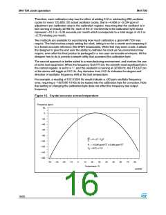
The oscillation rate of any crystal changes with temperature (see Figure 12). Most clock
chips compensate for crystal frequency and temperature shift error with cumbersome trim
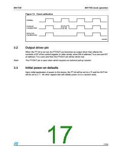
capacitors. The M41T00 design, however, employs periodic counter correction. The
calibration circuit adds or subtracts counts from the oscillator divider circuit at the divide by
256 stage, as shown in Figure 13. The number of times pulses are blanked (subtracted,
negative calibration) or split (added, positive calibration) depends upon the value loaded into
the five-bit calibration byte found in the control register. Adding counts speeds the clock up,
subtracting counts slows the clock down.
The calibration byte occupies the five lower order bits (D4-D0) in the control register (addr
7). This byte can be set to represent any value between 0 and 31 in binary form. Bit D5 is a
sign bit; '1' indicates positive calibration, '0' indicates negative calibration. Calibration occurs
within a 64minute cycle. The first 62 minutes in the cycle may, once per minute, have one
second either shortened by 128 or lengthened by 256 oscillator cycles. If a binary '1' is
loaded into the register, only the first 2 minutes in the 64 minute cycle will be modified; if a
binary 6 is loaded, the first 12 will be affected, and so on.
15/25

 STMICROELECTRONICS [ ST ]