M41T00
DC and AC parameters
5
DC and AC parameters
This section summarizes the operating and measurement conditions, as well as the dc and
ac characteristics of the device. The parameters in the following DC and AC characteristic
tables are derived from tests performed under the measurement conditions listed in the
relevant tables. Designers should check that the operating conditions in their projects match
the measurement conditions when using the quoted parameters.
(1)
Table 7.
Operating and AC measurement conditions
Parameter
M41T00
Supply voltage (VCC
)
2.0 to 5.5 V
Ambient operating temperature (TA)
Load capacitance (CL)
-40 to 85 °C
100 pF
Input rise and fall times
≤ 5 ns
Input pulse voltages
0.2 VCC to 0.8 VCC
0.3 VCC to 0.7 VCC
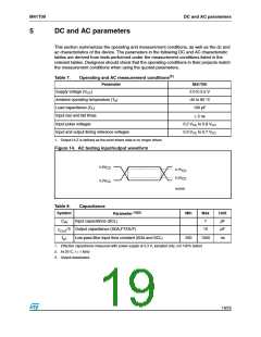
Input and output timing reference voltages
1. Output Hi-Z is defined as the point where data is no longer driven.
Figure 14. AC testing input/output waveform
0.8V
CC
0.7V
0.3V
CC
CC
0.2V
CC
AI02568
Table 8.
Symbol
Capacitance
Parameter (1)(2)
Min
Max
7
Unit
pF
CIN
Input capacitance (SCL)
(3)
Output capacitance (SDA,FT/OUT)
10
pF
C
OUT
tLP
Low-pass filter input time constant (SDA and SCL)
250
1000
ns
1. Effective capacitance measured with power supply at 3.3 V; sampled only, not 100% tested
2. At 25°C, f = 1 MHz
3. Output deselected.
19/25

 STMICROELECTRONICS [ ST ]