L6599
Application information
7
Application information
The L6599 is an advanced double-ended controller specific for resonant half-bridge
topology. In these converters the switches (MOSFETs) of the half-bridge leg are alternately
switched on and OFF (180° out-of-phase) for exactly the same time. This is commonly
referred to as operation at "50% duty cycle", although the real duty cycle, that is the ratio of
the ON-time of either switch to the switching period, is actually less than 50%. The reason is
that there is an internally fixed dead-time T , inserted between the turn-OFF of either
D
MOSFET and the turn-ON of the other one, where both MOSFETs are OFF. This dead- time
is essential in order for the converter to work correctly: it will ensure soft-switching and
enable high-frequency operation with high efficiency and low EMI emissions.
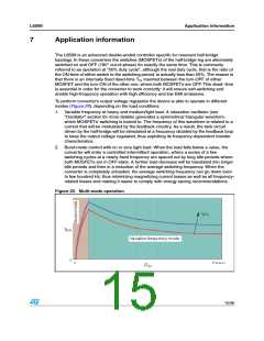
To perform converter's output voltage regulation the device is able to operate in different
modes (Figure 20), depending on the load conditions:
1. Variable frequency at heavy and medium/light load. A relaxation oscillator (see
"Oscillator" section for more details) generates a symmetrical triangular waveform,
which MOSFETs' switching is locked to. The frequency of this waveform is related to a
current that will be modulated by the feedback circuitry. As a result, the tank circuit
driven by the half-bridge will be stimulated at a frequency dictated by the feedback loop
to keep the output voltage regulated, thus exploiting its frequency-dependent transfer
characteristics.
2. Burst-mode control with no or very light load. When the load falls below a value, the
converter will enter a controlled intermittent operation, where a series of a few
switching cycles at a nearly fixed frequency are spaced out by long idle periods where
both MOSFETs are in OFF-state. A further load decrease will be translated into longer
idle periods and then in a reduction of the average switching frequency. When the
converter is completely unloaded, the average switching frequency can go down even
to few hundred Hz, thus minimizing magnetizing current losses as well as all frequency-
related losses and making it easier to comply with energy saving recommendations.
Figure 20. Multi-mode operation
15/36

 STMICROELECTRONICS [ ST ]