ACS102-6T
1 Characteristics
Table 3.
Symbol
Static electrical characteristics
Test conditions
Value
Unit
V
(1)
(1)
(1)
ITM= 0.3 A, tp = 380 µs
Tj = 25 °C
MAX
MAX
MAX
1.2
0.80
500
VTM
VTO
RD
Tj = 125 °C
Tj = 125 °C
V
mΩ
Tj = 25 °C
2
µA
IDRM
IRRM
VOUT = 600 V
MAX
Tj = 125 °C
0.2
mA
1. for both polarities of OUT referenced to COM
Table 4.
Symbol
Rth (j-l)
Thermal resistance
Parameter
Value
Unit
Junction to lead (AC)
Junction to ambient
TO-92
TO-92
S = 40 mm² SO-8
60
°C/W
150
150
Rth (j-a)
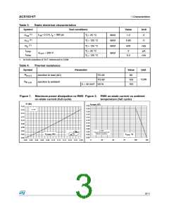
Figure 1. Maximum power dissipation vs RMS Figure 2. RMS on-state current vs ambient
on-state current (full cycle) temperature (full cycle)
P (W)
0.22 IT(RMS) (A)
0.18
0.16
0.14
0.12
0.10
0.08
0.06
0.04
0.02
0.00
0.20
0.18
0.16
0.14
0.12
0.10
0.08
0.06
α=180°
a=180°
Printed circuit board FR4
180°
0.04
0.02
0.00
Natural convection
IT(RMS) (A)
Tamb °C
0
25
50
75
100
125
0.00 0.02 0.04 0.06 0.08 0.10 0.12 0.14 0.16 0.18 0.20
3/11

 STMICROELECTRONICS [ ST ]