ST24/25C02, ST24C02R, ST24/25W02
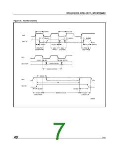
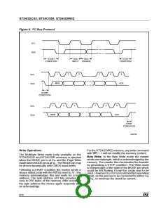
Figure 6. I2C Bus Protocol
SCL
SDA
START
SDA
SDA
STOP
CONDITION
INPUT CHANGE
CONDITION
1
2
3
7
8
9
SCL
SDA
ACK
MSB
START
CONDITION
1
2
3
7
8
9
SCL
SDA
MSB
ACK
STOP
CONDITION
AI00792
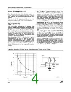
Write Operations
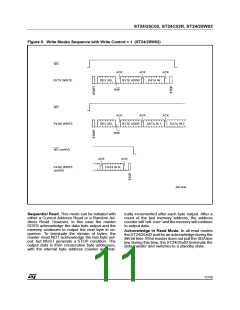
For the ST24/25W02 versions, any write command
with WC = 1 will not modify the memory content.
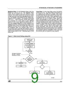
The Multibyte Write mode (only available on the
ST24/25C02 and ST24C02R versions) is selected
when the MODE pin is at VIH and the Page Write
mode whenMODEpin isat VIL. The MODEpinmay
be driven dynamically with CMOS input levels.
Byte Write. In the Byte Write mode the master
sends one data byte, which isacknowledged by the
memory. The master then terminates the transfer
by generating a STOP condition. The Write mode
is independant of the state of the MODE pin which
could be left floating if only this mode was to be
used. However it is not a recommended operating
mode, as this pin has to be connected to either VIH
or VIL, to minimize the stand-by current.
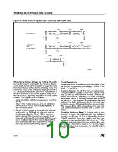
Following a START condition the master sends a
device select code with the RW bit reset to ’0’. The
memory acknowledges this and waits for a byte
address. The byte address of 8 bits provides ac-
cess to 256 bytes of the memory. After receipt of
the byte address the device again responds with
an acknowledge.
8/16

 STMICROELECTRONICS [ ST ]