ST24/25C02, ST24C02R, ST24/25W02
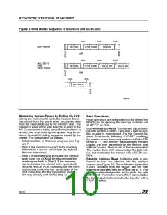
Figure 8. Write Modes Sequence (ST24/25C02 and ST24C02R)
ACK
ACK
ACK
ACK
BYTE WRITE
DEV SEL
BYTE ADDR
DATA IN
R/W
ACK
BYTE ADDR
ACK
MULTIBYTE
AND
DEV SEL
DATA IN 1
DATA IN 2
PAGE WRITE
R/W
ACK
ACK
DATA IN N
AI00793
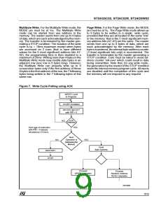
Minimizing System Delays by Polling On ACK.
During the internal write cycle, the memory discon-
nects itself from the bus in order to copy the data
from the internal latches to the memory cells. The
maximum value of the write time (tW) is given in the
AC Characteristics table, since the typical time is
shorter, the time seen by the system may be re-
duced by an ACK polling sequence issued by the
master. The sequence is as follows:
– Initial condition: a Write is in progress (see Fig-
ure 7).
– Step 1: the master issues a START condition
followed by a device select byte (1st byte of
the new instruction).
– Step 2: if the memory is busy with the internal
write cycle, no ACK will be returned and the
master goes back to Step 1. If the memory
has terminated the internal write cycle, it will
respond with an ACK, indicating that the mem-
ory is ready to receive the second part of the
next instruction (the first byte of this instruc-
tion was already sent during Step 1).
Read Operations
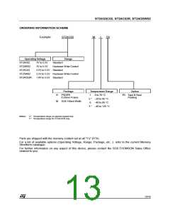
Readoperations areindependentof thestateof the
MODE pin. On delivery, the memory content is set
at all "1’s" (or FFh).
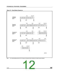
Current Address Read. The memory has an inter-
nal byte address counter. Each time a byte is read,
this counter is incremented. For the Current Ad-
dress Read mode, following a START condition,
the master sends a memory address with the RW
bit set to ’1’. The memory acknowledges this and
outputs the byte addressed by the internal byte
address counter. This counter is then incremented.
The master does NOT acknowledge the byte out-
put, but terminates the transfer with a STOP con-
dition.
Random Address Read. A dummy write is per-
formed to load the address into the address
counter, see Figure 10. This is followed by another
START condition from the master and the byte
address is repeated with the RW bit set to ’1’. The
memory acknowledges this and outputs the byte
addressed. The master have to NOT acknowledge
the byte output, but terminates the transfer with a
STOP condition.
10/16

 STMICROELECTRONICS [ ST ]