CXD1185CQ/CR
Description of Functions
1. Internal registers
The CXD1185C possesses 16 internal registers. The CPU can control the CXD1185C by reading and
writing these registers.
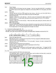
A summary of the registers is provided below.
Address
Read
Write
0
1
2
3
4
5
6
7
8
9
A
B
C
D
E
F
Status
Command
SCSI data
←
Interrupt request 1
Interrupt request 2
SCSI control monitor
FIFO status
<
>
Environment setting
Selection/reset timer
<
>
SCSI ID
←
←
←
←
←
←
←
←
←
←
Transfer byte counter (low)
Transfer byte counter (middle)
Transfer byte counter (high)
Interrupt authorization 1
Interrupt authorization 2
Mode
Sync transfer control
SCSI bus control
I/O port
<
> No register assigned to this address.
1-1. Status register (R0 : R)
This register is used to monitor the status of the CXD1185C.
7
6
5
4
3
2
1
0
MRST MDBP
INIT
TARG TRBZ MIRQ
CIP
MRST : Monitors the SCSI bus RST signal, positive logic.
MDBP : Monitors the SCSI bus DBP signal, positive logic.
INIT
: “1” when the CXD1185C is in initiator status.
When this bit is set to “1”, commands which are valid in target status and in initiator status are
accepted.
TARG : “1” when the CXD1185C is in target status.
When this bit is set to “1”, commands which are valid in initiator status and in target status are
accepted.
TRBZ : When this bit is set to “1”, it indicates that the transfer byte counter count is zero.
MIRQ : Monitors the interrupt request signal (IRQ signal).
This bit is set whenever interrupt request occurs and cleared once interrupt request 1 register and
interrupt 2 register are read. This bit is not affected by the content of the interrupt authorization
register. The logic level of this bit is not affected by the SIRM bit in the environment setting register.
CIP
: Indicates that a chip command is being executed.
While this bit is “1”, no new commands can be written to the command register, with the exception
of the “Reset Chip” command.
—11—

 SONY [ SONY CORPORATION ]