Highly Integrated Full Featured Hi-Speed USB 2.0 ULPI Transceiver
Datasheet
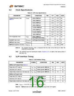
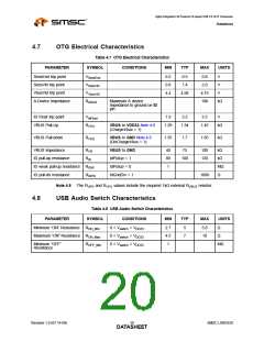
4.7
OTG Electrical Characteristics
Table 4.7 OTG Electrical Characteristics
PARAMETER
SYMBOL
CONDITIONS
MIN
TYP
MAX
UNITS
SessEnd trip point
SessVld trip point
VbusVld trip point
A-Device Impedance
VSessEnd
VSessVld
VVbusVld
RIdGnd
0.2
0.8
4.4
0.5
1.4
0.8
2.0
V
V
4.58
4.75
100
V
Maximum A device
Impedance to ground on ID
pin
kΩ
ID Float trip point
VBUS Pull-Up
VIdFloat
RVPU
1.9
2.2
2.5
V
VBUS to VDD33 Note 4.8
(ChargeVbus = 1)
1.29
1.34
1.45
kΩ
VBUS Pull-down
RVPD
VBUS to GND Note 4.8
(DisChargeVbus = 1)
1.55
1.7
1.85
kΩ
VBUS Impedance
RVB
RID
VBUS to GND
IdPullup = 1
IdPullup = 0
IdGndDrv = 1
40
80
1
75
100
120
kΩ
kΩ
MΩ
Ω
ID pull-up resistance
100
ID weak pull-up resistance RIDW
ID pull-dn resistance RIDPD
1000
Note 4.8 The RVPD and RVPU values include the required 1kΩ external RVBUS resistor.
4.8
USB Audio Switch Characteristics
Table 4.8 USB Audio Switch Characteristics
PARAMETER
SYMBOL
CONDITIONS
MIN
TYP
MAX
UNITS
Minimum “ON” Resistance RON_Min
Maximum “ON” Resistance RON_Max
0 < Vswitch < VDD33
0 < Vswitch < VDD33
0 < Vswitch < VDD33
2.7
4.5
1
5
7
5.8
10
Ω
Ω
Minimum “OFF”
Resistance
ROFF_Min
MΩ
Revision 1.0 (07-14-09)
SMSC USB3320
DATA2S0HEET

 SMSC [ SMSC CORPORATION ]