USB 2.0 Hi-Speed 2-Port Hub Controller
Datasheet
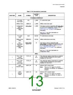
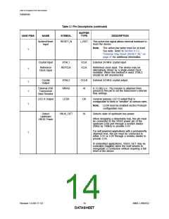
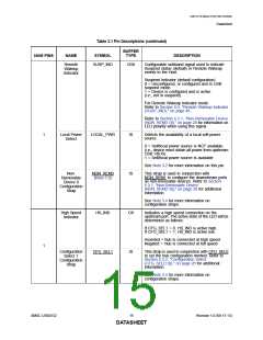
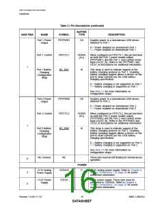
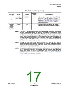
Table 3.1 Pin Descriptions (continued)
BUFFER
NUM PINS
NAME
SYMBOL
TYPE
DESCRIPTION
SystemReset
Input
RESET_N
I_RST
This active-low signal allows external hardware to
reset the device.
Note:
The active-low pulse must be at least
5us wide. Refer to Section 8.3.2,
"External Chip Reset (RESET_N)," on
page 47 for additional information.
1
Crystal Input
XTAL1
ICLK
ICLK
External 24 MHz crystal input
Reference
Clock Input
REFCLK
Reference clock input. The device may be
alternatively driven by a single-ended clock
oscillator. When this method is used, XTAL2
should be left unconnected.
1
Crystal
Output
XTAL2
RBIAS
OCLK
AI
External 24 MHz crystal output
1
1
External USB
Transceiver
Bias Resistor
A 12.0kΩ (+/- 1%) resistor is attached from
ground to this pin to set the transceiver’s internal
bias settings.
LED 0 Output
LED0
O8
IS
General purpose LED 0 output that is
configurable to blink or “breathe” at various rates.
1
Note:
LED0 must be enabled via the Protouch
configuration tool.
Detect
VBUS_DET
Detects state of upstream bus power.
Upstream
VBUS Power
When designing a detachable hub, this pin must
be connected to the VBUS power pin of the
upstream USB port through a resistor divider
(50kΩ by 100kΩ) to provide 3.3V.
For self-powered applications with a permanently
attached host, this pin must be connected to
either 3.3V or 5.0V through a resistor divider to
provide 3.3V.
1
In embedded applications, VBUS_DET may be
controlled (toggled) when the host desires to
renegotiate a connection without requiring a full
reset of the device.
Revision 1.0 (06-17-13)
14
SMSC USB2532
DATASHEET

 SMSC [ SMSC CORPORATION ]