USB 2.0 Hi-Speed 2-Port Hub Controller
Datasheet
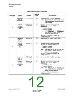
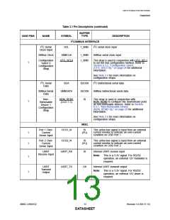
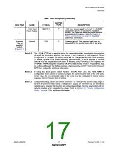
Table 3.1 Pin Descriptions (continued)
BUFFER
NUM PINS
NAME
SYMBOL
TYPE
DESCRIPTION
I2C/SMBUS INTERFACE
I2C Serial
SCL
I_SMB
I2C serial clock input
Clock Input
SMBus Clock
SMBCLK
I_SMB
I_SMB
SMBus serial clock input
Configuration
Select 0
Configuration
Strap
CFG_SEL0
This strap is used in conjunction with CFG_SEL1
to set the hub configuration method. Refer to
Section 6.3.2, "Configuration Select
(CFG_SEL[1:0])," on page 28 for additional
information.
1
See Note 3.4 for more information on
configuration straps.
I2C Serial
Data
SDA
IS/OD8
IS/OD8
IS
I2C bidirectional serial data
SMBus Serial
Data
SMBDATA
SMBus bidirectional serial data
Non-
Removable
Device 1
Configuration
Strap
NON_REM1
(Note 3.3)
This strap is used in conjunction with
NON_REM0 to configure the downstream ports
as non-removable devices. Refer to Section
6.3.1, "Non-Removable Device
(NON_REM[1:0])," on page 28 for additional
information.
1
See Note 3.4 for more information on
configuration straps.
MISC.
Port 1 Over-
Current
Sense Input
OCS1_N
OCS2_N
UART_RX
IS
(PU)
This active-low signal is input from an external
current monitor to indicate an over-current
condition on USB Port 1.
1
1
Port 2 Over-
Current
Sense Input
IS
(PU)
This active-low signal is input from an external
current monitor to indicate an over-current
condition on USB Port 2.
UART
IS
Internal UART receive input
Receive Input
Note:
This is a 3.3V signal. For RS232
operation, an external 12V translator is
required.
1
1
UART
Transmit
Output
UART_TX
O8
Internal UART transmit output
Note: This is a 3.3V signal. For RS232
operation, an external 12V driver is
required.
SMSC USB2532
13
Revision 1.0 (06-17-13)
DATASHEET

 SMSC [ SMSC CORPORATION ]