USB 2.0 Hi-Speed 2-Port Hub Controller
Datasheet
3.1
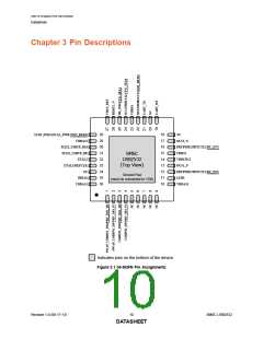
Pin Descriptions
This section provides a detailed description of each pin. The signals are arranged in functional groups
according to their associated interface.
The “_N” symbol in the signal name indicates that the active, or asserted, state occurs when the signal
is at a low voltage level. For example, RESET_N indicates that the reset signal is active low. When
“_N” is not present after the signal name, the signal is asserted when at the high voltage level.
The terms assertion and negation are used exclusively. This is done to avoid confusion when working
with a mixture of “active low” and “active high” signals. The term assert, or assertion, indicates that a
signal is active, independent of whether that level is represented by a high or low voltage. The term
negate, or negation, indicates that a signal is inactive.
Note: The buffer type for each signal is indicated in the BUFFER TYPE column of Table 3.1. A
description of the buffer types is provided in Section 3.3.
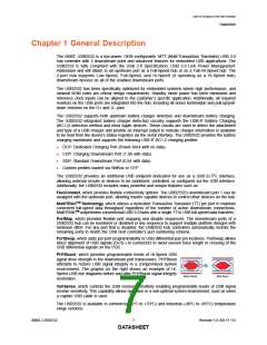
Note: Compatibility with the SMSC UCS100x family of USB port power controllers requires the
UCS100x be connected on Port 1 of the USB2532. Additionally, both PRTPWR1 and OCS1_N
must be pulled high at Power-On Reset (POR).
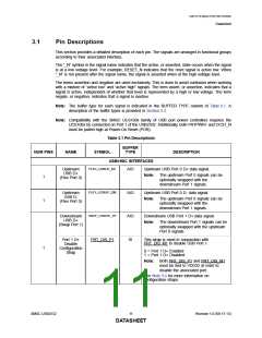
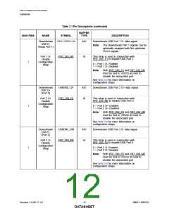
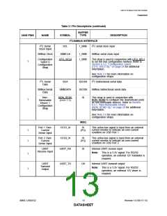
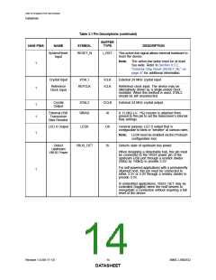
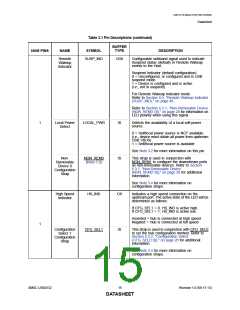
Table 3.1 Pin Descriptions
BUFFER
TYPE
NUM PINS
NAME
SYMBOL
DESCRIPTION
USB/HSIC INTERFACES
FLEX_USBUP_DP
FLEX_USBUP_DM
SWAP_USBDN1_DP
Upstream
USB D+
(Flex Port 0)
AIO
AIO
AIO
IS
Upstream USB Port 0 D+ data signal.
Note:
The upstream Port 0 signals can be
optionally swapped with the
downstream Port 1 signals.
1
1
Upstream
USB D-
(Flex Port 0)
Upstream USB Port 0 D- data signal.
Note:
The upstream Port 0 signals can be
optionally swapped with the
downstream Port 1 signals.
Downstream
USB D+
(Swap Port 1)
Downstream USB Port 1 D+ data signal.
Note:
The downstream Port 1 signals can be
optionally swapped with the upstream
Port 0 signals.
Port 1 D+
Disable
Configuration
Strap
PRT_DIS_P1
This strap is used in conjunction with
PRT_DIS_M1 to disable USB Port 1.
1
0 = Port 1 D+ Enabled
1 = Port 1 D+ Disabled
Note:
Both PRT_DIS_P1 and PRT_DIS_M1
must be tied to VDD33 at reset to
disable the associated port.
See Note 3.4 for more information on
configuration straps.
SMSC USB2532
11
Revision 1.0 (06-17-13)
DATASHEET

 SMSC [ SMSC CORPORATION ]