USB 2.0 Hi-Speed 2-Port Hub Controller
Datasheet
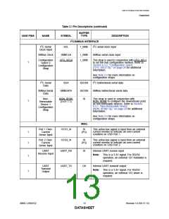
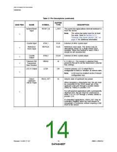
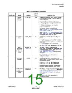
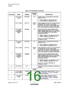
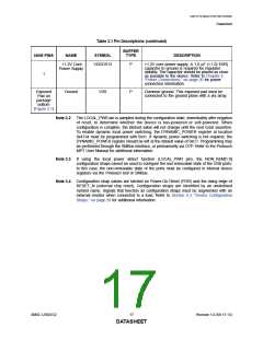
Table 3.1 Pin Descriptions (continued)
BUFFER
NUM PINS
NAME
SYMBOL
TYPE
DESCRIPTION
+1.2V Core
Power Supply
VDDCR12
P
+1.2V core power supply. A 1.0 μF (<1 Ω ESR)
capacitor to ground is required for regulator
stability. The capacitor should be placed as close
as possible to the device. Refer to Chapter 4,
"Power Connections," on page 20 for power
connection information.
1
Exposed
Pad on
Ground
VSS
P
Common ground. This exposed pad must be
connected to the ground plane with a via array.
package
bottom
(Figure 3.1)
Note 3.2 The LOCAL_PWR pin is sampled during the configuration state, immediately after negation
of reset, to determine whether the device is bus-powered or self-powered. When
configuration is complete, the latched value will not change until the next reset assertion.
To enable dynamic local power switching, the DYNAMIC_POWER register at location
0x4134 must be programmed with 0x41. If dynamic power switching is not required, the
DYNAMIC_POWER register should be left at the default value of 0xC1. Programming may
be performed through the SMBus interface, or permanently via OTP. Refer to the Protouch
MPT User Manual for additional information.
Note 3.3 If using the local power detect function (LOCAL_PWR pin), the NON_REM[1:0]
configuration straps cannot be used to configure the non-removable state of the USB ports.
In this case, the non-removable state of the ports must be configured in internal device
registers via the Protouch tool or SMBus.
Note 3.4 Configuration strap values are latched on Power-On Reset (POR) and the rising edge of
RESET_N (external chip reset). Configuration straps are identified by an underlined
symbol name. Signals that function as configuration straps must be augmented with an
external resistor when connected to a load. Refer to Section 6.3, "Device Configuration
Straps," on page 28 for additional information.
SMSC USB2532
17
Revision 1.0 (06-17-13)
DATASHEET

 SMSC [ SMSC CORPORATION ]