USB 2.0 Hi-Speed 2-Port Hub Controller
Datasheet
Table 3.1 Pin Descriptions (continued)
BUFFER
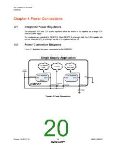
NUM PINS
NAME
SYMBOL
TYPE
DESCRIPTION
Port 1 Power
Output
PRTPWR1
O8
Enables power to a downstream USB device
attached to Port 1.
0 = Power disabled on downstream Port 1
1 = Power enabled on downstream Port 1
Port 1 Control
PRTCTL1
BC_EN1
OD8/IS
(PU)
When configured as PRTCTL1, this pin functions
as both the Port 1 power enable output
(PRTPWR1) and the Port 1 over-current sense
input (OCS1_N). Refer to the PRTPWR1 and
OCS1_N descriptions for additional information.
1
Port 1 Battery
Charging
Configuration
IS
This strap is used to indicate support of the
battery charging protocol on Port 1. Enabling
battery charging support allows a device on the
port to draw currents per the USB battery
charging specification.
Strap
0 = Battery charging is not supported on Port 1
1 = Battery charging is supported on Port 1
See Note 3.4 for more information on
configuration straps.
Port 2 Power
Output
PRTPWR2
PRTCTL2
BC_EN2
O8
Enables power to a downstream USB device
attached to Port 2.
0 = Power disabled on downstream Port 2
1 = Power enabled on downstream Port 2
Port 2 Control
OD8/IS
(PU)
When configured as PRTCTL2, this pin functions
as both the Port 2 power enable output
(PRTPWR2) and the Port 2 over-current sense
input (OCS2_N). Refer to the PRTPWR2 and
OCS2_N descriptions for additional information.
1
Port 2 Battery
Charging
Configuration
IS
This strap is used to indicate support of the
battery charging protocol on Port 2. Enabling
battery charging support allows a device on the
port to draw currents per the USB battery
charging specification.
Strap
0 = Battery charging is not supported on Port 2
1 = Battery charging is supported on Port 2
See Note 3.4 for more information on
configuration straps.
No Connect
NC
-
These pins must be left floating for normal device
operation.
8
POWER
+3.3V Analog
Power Supply
VDDA33
VDD33
P
+3.3V analog power supply. Refer to Chapter 4,
"Power Connections," on page 20 for power
connection information.
3
2
+3.3V Power
Supply
P
+3.3V power supply. These pins must be
connected to VDDA33. Refer to Chapter 4,
"Power Connections," on page 20 for power
connection information.
Revision 1.0 (06-17-13)
16
SMSC USB2532
DATASHEET

 SMSC [ SMSC CORPORATION ]