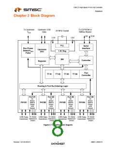
USB 2.0 High-Speed 4-Port Hub Controller
Datasheet
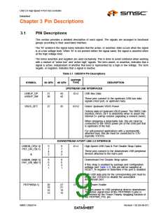
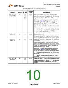
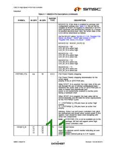
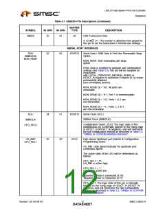
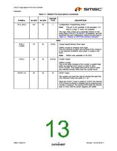
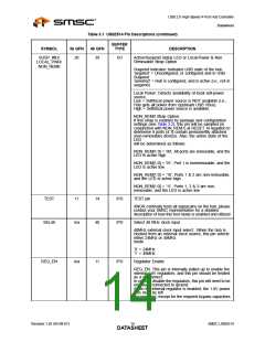
Table 3.1 USB2514 Pin Descriptions (continued)
BUFFER
TYPE
SYMBOL
36 QFN
48 QFN
DESCRIPTION
USB Transceiver Bias
RBIAS
35
47
I-R
A 12.0kΩ (+/- 1%) resistor is attached from ground to
this pin to set the transceiver’s internal bias settings.
SERIAL PORT INTERFACE
SDA/
SMBDATA/
NON_REM1
22
29
I/OSD12
Serial Data / SMB Data & Port Non Removable Strap
Option
NON_REM1: Non removable port strap
option.
If this strap is enabled by package and configuration
settings (see Table 3.2), this pin will be sampled (in
conjunction
with LOCAL_PWR/SUSP_IND/NON_REM0) at
RESET_N negation to determine if imports [4:1] contain
permanently attached
(non-removable) devices:
NON_REM[1:0] = ‘00’, All ports are
removable,
NON_REM[1:0] = ‘01’, Port 1 is nonremovable,
NON_REM[1:0] = ‘10’, Ports 1 & 2 are
non-removable,
NON_REM[1:0] = ‘11’, Ports 1, 2 & 3
are non-removable
SCL/
24
31
I/OSD12
Serial Clock (SCL)
SMBus Clock (SMBCLK)
SMBCLK/
CFG_SEL0
Configuration Select_SEL0: The logic state of this
multifunction pin is internally latched on the rising edge
of RESET_N (RESET_N negation), and will determine
the hub configuration method as described in Table 3.2,
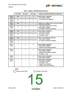
"SMBus or EEPROM Interface Behavior".
HS_IND/
CFG_SEL1
25
32
I/O12
High-Speed Upstream port indictor & Configuration
Programming Select
HS_IND: High Speed Indicator for upstream port
connection speed.
The active state of the LED will be determined as
follows:
CFG_SEL1 = ‘0’,
HS_IND is active high,
CFG_SEL1 = ‘1’,
HS_IND is active low,
‘Asserted’ = Hub is connected at HS
‘Negated’ = Hub is connected at FS
CFG_SEL1: The logic state of this pin is internally
latched on the rising edge of RESET_N (RESET_N
negation), and will determine the hub configuration
method as described in Table 3.2, "SMBus or EEPROM
Interface Behavior".
Revision 1.92 (05-08-07)
SMSC USB2514
DATA1S2HEET

 SMSC [ SMSC CORPORATION ]