USB 2.0 High-Speed 4-Port Hub Controller
Datasheet
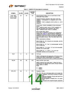
Table 3.1 USB2514 Pin Descriptions (continued)
BUFFER
TYPE
SYMBOL
36 QFN
48 QFN
DESCRIPTION
SUSP_IND/
LOCAL_PWR/
NON_REM0
28
39
I/O
Active/Suspend status LED or Local-Power & Non
Removable Strap Option
Suspend Indicator: Indicates USB state of the hub.
‘negated’ = Unconfigured, or configured and in USB
Suspend
‘asserted’ = Hub is configured, and is active (i.e., not in
suspend)
Local Power: Detects availability of local self-power
source.
Low = Self/local power source is NOT available (i.e.,
Hub gets all power from Upstream USB VBus).
High = Self/local power source is available.
NON_REM0 Strap Option:
If this strap is enabled by package and configuration
settings (see Table 3.2), this pin will be sampled (in
conjunction with NON_REM1) at RESET_N negation to
determine if ports [4:1] contain permanently attached
(non-removable) devices. Also, the active state of the
LED
will be determined as follows:
NON_REM[1:0] = ‘00’, All ports are removable, and the
LED is active high
NON_REM[1:0] = ‘01’, Port 1 is nonremovable, and the
LED is active low
NON_REM[1:0] = ‘10’, Ports 1 & 2 are non-removable,
and the LED is active high
NON_REM[1:0] = ‘11’, Ports 1, 2 & 3 are non-
removable, and the LED is active low
TEST
11
14
40
IPD
IPD
TEST pin
XNOR continuity tests all signal pins on the hub, please
contact your SMSC representative for a detailed
description of how this test mode is enabled and utilized.
SEL48
n/a
Select 48 MHz clock input
48MHz external clock input select:. When the hub is
clocked from an external clock source, this pin selects
either 24MHz or 48MHz
mode.
‘0’ = 24MHz
‘1’ = 48MHz
REG_EN
n/a
11
IPU
Regulator Enable
REG_EN: This pin is internally pulled up to enable the
internal 1.8V regulators, and this pin should be treated
as a no-connect.
In order to disable the regulators, this pin will need to be
externally connected to ground.
When the internal regulator is enabled, the 1.8V power
pins must be left
unconnected, except for the required bypass capacitors.
Revision 1.92 (05-08-07)
SMSC USB2514
DATA1S4HEET

 SMSC [ SMSC CORPORATION ]