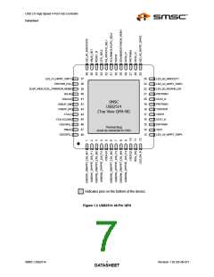
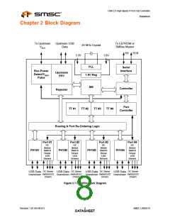
USB 2.0 High-Speed 4-Port Hub Controller
Datasheet
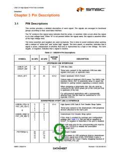
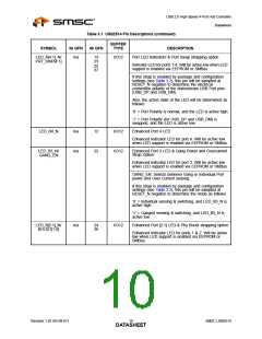
Table 3.1 USB2514 Pin Descriptions (continued)
BUFFER
TYPE
SYMBOL
36 QFN
48 QFN
DESCRIPTION
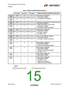
BOOST[1:0], If this strap is enabled by package and
configuration settings (see Table 3.2), this pin will be
sampled at RESET_N negation to determine if all PHY
ports (upstream and downstream) operate at a normal
or boosted electrical level. Also, the active state of the
LEDs will be determined as follows:
See for BOOST values: Section 4.3.1.26, "Register F6h:
Boost_Up (Reset = 0x00)" and Section 4.3.1.27,
"Register F8h: Boost_4:0 (Reset = 0x00)".
BOOST[1:0] = BOOST_IOUT[1:0]
BOOST[1:0] = ‘00’,
LED_B2_N is active high,
LED_B1_N is active high.
BOOST[1:0] = ‘01’,
LED_B2_N is active high,
LED_B1_N is active low.
BOOST[1:0] = ‘10’,
LED_B2_N is active low,
LED_B1_N is active high.
BOOST[1:0] = ‘11’,
LED_B2_N is active low,
LED_B1_N is active low.
PRTPWR_POL
n/a
38
I/O12
Port Power Polarity strapping
Port Power Polarity strapping determination for the
active signal
polarity of the [4:1]PRTPWR pins.
While RESET_N is asserted, the logic state of this pin
will (through the use of internal combinatorial logic)
determine the active state of the [4:1]PRTPWR pins in
order to ensure that downstream port
power is not inadvertently enabled to inactive ports
during a hardware reset.
When RESET_N is negated, the logic value will be
latched internally, and will retain the active signal polarity
for the PRTPWR[4:1] pins.
‘1’ = PRTPWR[4:1]_P/N pins have an active ‘high’
polarity
‘0’ = PRTPWR[4:1]_P/N pins have an active ‘low’
polarity
Warning: Active Low port power controllers may glitch
the downstream port power when system power is first
applied. Care should be taken when designing with
active low components!
Note:
If PRTPWR_POL is not an available pin on the
package, the hub will support active high
power controllers only!
OCS[4:1]_N
21
19
17
13
28
26
20
16
IPU
Over Current Sense
Input from external current monitor indicating an over-
current condition.
{Note: Contains internal pull-up to 3.3V supply}
SMSC USB2514
Revision 1.92 (05-08-07)
DATAS11HEET

 SMSC [ SMSC CORPORATION ]