USB 2.0 High-Speed 4-Port Hub Controller
Datasheet
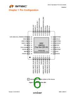
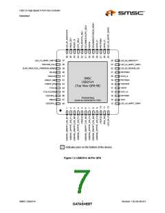
Chapter 3 Pin Descriptions
3.1
PIN Descriptions
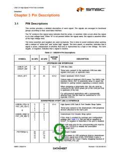
This section provides a detailed description of each signal. The signals are arranged in functional
groups according to their associated interface.
The “N” symbol in the signal name indicates that the active, or asserted, state occurs when the signal
is at a low voltage level. When “N” is not present before the signal name, the signal is asserted when
at the high voltage level.
The terms assertion and negation are used exclusively. This is done to avoid confusion when working
with a mixture of “active low” and “active high” signals. The term assert, or assertion, indicates that a
signal is active, independent of whether that level is represented by a high or low voltage. The term
negate, or negation, indicates that a signal is inactive.
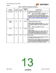
Table 3.1 USB2514 Pin Descriptions
BUFFER
TYPE
SYMBOL
36 QFN
48 QFN
DESCRIPTION
UPSTREAM USB INTERFACES
USBUP_DP
USBUP_DM
31
30
43
42
IO-U
USB Bus Data
These pins connect to the upstream USB bus data
signals (Host port, or upstream hub).
VBUS_DET
27
35
I/O12
Detect Upstream VBUS Power
Detects state of Upstream VBUS power. The SMSC Hub
monitors VBUS_DET to determine when to assert the
internal D+ pull-up resistor (signaling a connect event).
When designing a detachable hub, this pin must be
connected to the VBUS power pin of the USB port that
is upstream of the hub.
For self-powered applications with a permanently
attached host, this pin must be connected to 3.3V
(typically VDD33).
DOWNSTREAM 4-PORT USB 2.0 INTERFACE
USBDN_DP[4:1]/
PRT_DIS_P[4:1]
9
7
4
2
9
7
4
2
IO-U
High-Speed USB Data & Port Disable Strap Option
These pins connect to the downstream USB peripheral
devices attached to the hub’s port.
&
8
6
3
1
8
6
3
1
Downstream Port Disable Strap option:
USBDN_DM[4:1]/
PRT_DIS_M[4:1]
If this strap is enabled by package and configuration
settings (see Table 3.2), this pin will be sampled at
RESET_N negation to determine if the port is disabled.
Both USB data pins for the corresponding port must be
tied to the VDDA33 to disable the associated
downstream port.
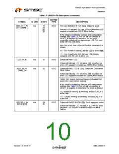
PRTPWR[4:1]
20
18
16
12
27
21
19
15
O12
USB Power Enable
Enables power to USB peripheral devices downstream.
The active signal level of the PRTPWR[4:1] pins is
determined by the Power Polarity Strapping function of
the PRTPWR_POL pin.
SMSC USB2514
9
Revision 1.92 (05-08-07)
DATASHEET

 SMSC [ SMSC CORPORATION ]