5th Generation Hi-Speed USB Flash Media and CIR Controller with Integrated Card Power FETs
Datasheet
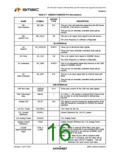
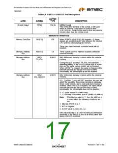
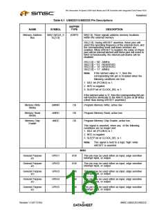
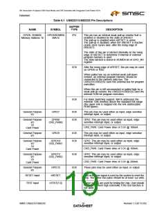
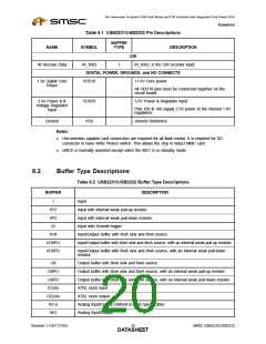
Table 6.1 USB2231/USB2232 Pin Descriptions
BUFFER
NAME
SYMBOL
TYPE
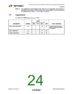
DESCRIPTION
CIR
IR_RXD, is the CIR receiver input.
IR Receive Data
IR_RXD
I
DIGITAL POWER, GROUNDS, and NO CONNECTS
1.8v Digital Core
Power
VDD18
VDD33
VSS
+1.8V Core power
All VDD18 pins must be connected together on the
circuit board.
3.3v Power & &
Voltage Regulator
Input
3.3V Power & Regulator Input.
Pins 100 & 108 supply 3.3V power to the internal 1.8V
regulators.
Ground
Ground Reference
Notes:
■
Hot-insertion capable card connectors are required for all flash media. It is required for SD
connector to have Write Protect switch. This allows the chip to detect MMC card.
■
nMCE is normally asserted except when the 8051 is in standby mode.
6.2
Buffer Type Descriptions
Table 6.2 USB2231/USB2232 Buffer Type Descriptions
BUFFER
DESCRIPTION
I
Input
IPU
Input with internal weak pull-up resistor.
IPD
Input with internal weak pull-down resistor.
IS
Input with Schmitt trigger
I/O8
I/O8PU
I/O8PD
Input/Output buffer with 8mA sink and 8mA source.
Input/Output buffer with 8mA sink and 8mA source, with an internal weak pull-up resistor.
Input/Output buffer with 8mA sink and 8mA source, with an internal weak pull-down
resistor.
O8
Output buffer with 8mA sink and 8mA source.
Output buffer with 8mA sink and 8mA source, with an internal weak pull-up resistor.
Output buffer with 8mA sink and 8mA source, with an internal weak pull-down resistor.
XTAL clock input
O8PU
O8PD
ICLKx
OCLKx
I/O-U
AIO
XTAL clock output
Analog Input/Output Defined in USB specification
Analog Input/Output
Revision 1.3 (07-12-05)
SMSC USB2231/USB2232
DATA2S0HEET

 SMSC [ SMSC CORPORATION ]