5th Generation Hi-Speed USB Flash Media and CIR Controller with Integrated Card Power FETs
Datasheet
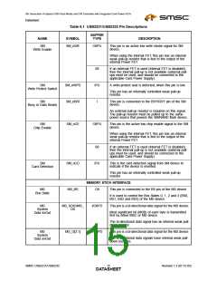
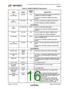
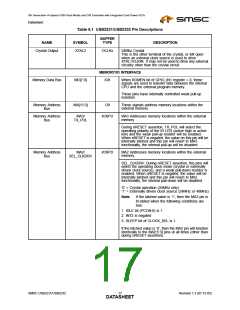
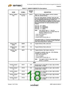
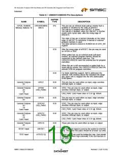
Table 6.1 USB2231/USB2232 Pin Descriptions
BUFFER
NAME
SYMBOL
TYPE
DESCRIPTION
GPIO6, ROMEN,
GPIO6/ROMEN
/MA16
IPU
This pin has an internal weak pull-up resistor that is
enabled or disabled by the state of nRESET.
The pull-up is enabled when nRESET is active.
The pull-up is disabled, when the nRESET is inactive
(some clock cycles later, after the rising edge of
nRESET).
Memory Address 16
The state of this pin is latched internally on the rising
edge of nRESET to determine if internal or external
program memory is used.
The state latched is stored in ROMEN bit of GPIO_IN1
register.
I/O8
After the rising edge of nRESET, this pin may be used
as GPIO6 or RXD.
When pulled low via an external weak pull-down
resistor, an external program memory should be
connected to the memory data bus. The
USB2231/USB2232 uses this external bus for program
execution.
When this pin is left unconnected or pulled high by a
weak pull-up resistor, the USB2231/USB2232 uses the
internal ROM for program execution.
I/O8
For Bank Switching support, MA16 addresses the
external 128k memory above the standard 64k range
(the upper 64k is mapped into the 64k addressable
ROM space)
General Purpose
I/O
GPIO7
I/O8
I/O8
This pin may be used either as input, edge sensitive
interrupt input, or output.
General Purpose
GPIO8/
GPIO: This pin may be used either as input, edge
sensitive interrupt input, or output.
I/O
Or
CRD_PWR0
CRD_PWR: Card Power drive of 3.3V @ 100mA.
Card Power
General Purpose
I/O
GPIO9
I/O8
I/O8
This pin may be used either as input, edge sensitive
interrupt input, or output.
General Purpose
GPIO10/
GPIO: This pin may be used either as input, edge
sensitive interrupt input, or output.
I/O
Or
CRD_PWR1
CRD_PWR: Card Power drive of 3.3V @ 100mA.
Card Power
General Purpose
GPIO11/
I/O8
GPIO: This pin may be used either as input, edge
sensitive interrupt input, or output.
I/O
Or
CRD_PWR2
CRD_PWR: Card Power drive of 3.3V @ 200mA.
These pins may be used either as input, or output.
Card Power
General Purpose
I/O
GPIO12
nRESET
I/O8
IS
I
RESET input
This active low signal is used by the system to reset the
chip. The active low pulse should be at least 1µs wide.
TEST Input
nTEST[1:0]
These signals are used for testing the chip. User should
normally tie them high externally, if the test function is
not used.
SMSC USB2231/USB2232
Revision 1.3 (07-12-05)
DATA1S9HEET

 SMSC [ SMSC CORPORATION ]