5th Generation Hi-Speed USB Flash Media and CIR Controller with Integrated Card Power FETs
Datasheet
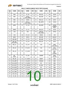
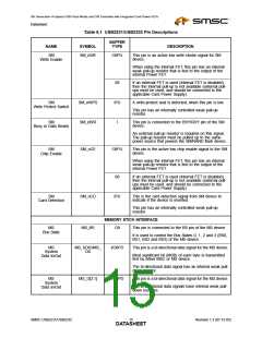
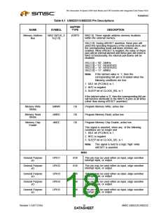
Table 6.1 USB2231/USB2232 Pin Descriptions
BUFFER
NAME
SYMBOL
TYPE
DESCRIPTION
CF
CF_nCD2
IPU
This card detection pin is connected to the ground on
the CF device, when the CF device is inserted.
Card Detection2
This pin has an internally controlled weak pull-up
resistor.
CF
CF_nCD1
IPU
This card detection pin is connected to ground on the
CF device, when the CF device is inserted.
Card Detection1
This pin has an internally controlled weak pull-up
resistor.
CF
CF_nRESET
CF_nIOR
O8
O8
O8
This pin is an active low hardware reset signal to CF
device.
Hardware Reset
CF
This pin is an active low read strobe signal for CF
device.
IO Read
CF
CF_nIOW
This pin is an active low write strobe signal for CF
device.
IO Write Strobe
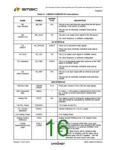
SmartMedia INTERFACE
SM
SM_nWP
SM_ALE
SM_CLE
SM_D[7:0]
SM_nRE
O8PD
O8PD
O8PD
I/O8PD
08PU
This pin is an active low write protect signal for the SM
device.
Write Protect
This pin has a weak pull-down resistor that is
permanently enabled
SM
This pin is an active high Address Latch Enable signal
for the SM device.
Address Strobe
This pin has a weak pull-down resistor that is
permanently enabled
SM
This pin is an active high Command Latch Enable signal
for the SM device.
Command Strobe
This pin has a weak pull-down resistor that is
permanently enabled
SM
These pins are the bi-directional data signal SM_D7-
SM_D0.
Data7-0
The bi-directional data signal has an internal weak pull-
down resistor.
SM
This pin is an active low read strobe signal for SM
device.
Read Enable
When using the internal FET, this pin has an internal
weak pull-up resistor that is tied to the output of the
internal Power FET.
08
If an external FET is used (Internal FET is disabled),
then the internal pull-up is not available (external pull-
ups must be used, and should be connected to the
applicable Card Power Supply).
Revision 1.3 (07-12-05)
SMSC USB2231/USB2232
DATA1S4HEET

 SMSC [ SMSC CORPORATION ]