4.1.5.4
DMA Mode Select, Bit 3
Writing to the DMA Mode Select bit has no effect on the operation of the UART. The RXRDY and TXRDY pins are
not available on this chip.
4.1.5.5
Reserved, Bits 4 - 5
Bits 4 to 5 are RESERVED. Reserved bits cannot be written and return 0 when read.
4.1.5.6
RCVR Trigger, Bits 6 - 7
The RCVR Trigger bits are used to set the trigger level for the RCVR FIFO interrupt (Table 6).
Table 6 - RCVR Trigger Encoding
RCVR
TRIGGER
RCVR FIFO Trigger Level
(BYTES)
Bit 7
0
0
1
1
Bit 6
0
1
0
1
1
4
8
14
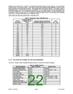
4.1.6 LINE CONTROL REGISTER (LCR)
The Line Control register (Address Offset = 3H, DLAB = 0, READ/WRITE) contains the formatting information for the
serial line.
4.1.6.1
Word Length Select, Bits 0 - 1
The Word Length Select bits specify the number of bits in each transmitted or received serial character. Note: the
Start, Stop and Parity bits are not included in the word length. The encoding of the Word Length bits is shown in
Table 7.
Table 7 - Word Length Encoding
WORD LENGTH
SELECT
WORD LENGTH (Bits)
Bit 1
Bit 0
0
0
1
1
0
1
0
1
5
6
7
8
4.1.6.2
Stop Bits, Bit 2
The Stop Bits bit specifies the number of stop bits in each transmitted or received serial character. Table 8 describes
the Stop Bits encoding.
Table 8 - STOP Bit Encoding
STOP BITS
WORD
NUMBER OF
LENGTH
STOP BITS
(Bit 2)
0
0
1
1
1
-
1
1.5
2
2
2
5 Bits
6 Bits
7 Bits
8 Bits
Note: The receiver ignores stop bits beyond the first, regardless of the number of stop bits used in transmitting.
SMSC DS – SP37E760
Page 18
Rev. 04/13/2001

 SMSC [ SMSC CORPORATION ]